80-0000010B OM
195
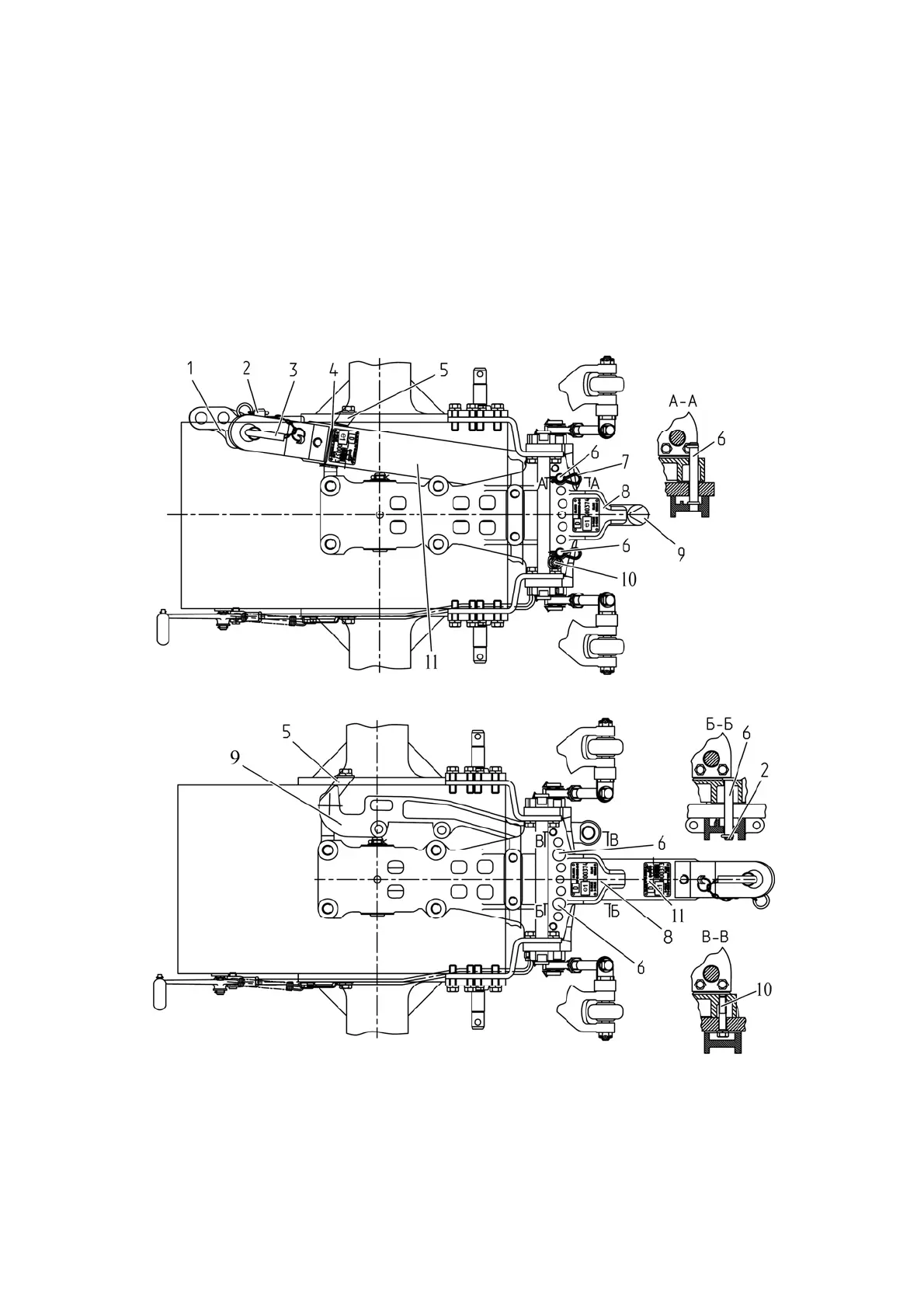
3.17.9 Resetting of pendulum and hydraulic hook in a combined device.
When working with combined device TSU-2М-02 one of hitch elements (hydraulic
hook or pendulum) is set in working position, and the other – in additional position, which
is not used during tractor operation. When working with tow hitch, with hydraulic hook 9
(figure 3.17.7) set to working position, pendulum 11 is secured from one side by pin 6, to
bracket 8 and is locked with cotter pin 7, and from the other side pendulum 11 is tied to
plate 5 with wire 4. Second pin 6, is locked in free bore of bracket 8. Bolt 10, intended for
locking hydraulic hook 9 in additional position, is screwed into free threaded bore of brack-
et 8. Eyebar 1, with pin 2 installed in it, is secured to pendulum 11 by means of pivot 3.
When working with tow hitch, with the pendulum set to working position, the hydraulic hook
is secured to bracket 8 by means of bolt 10, horn of the hydraulic hook lies on plate 5. Pins
6, installed in bracket 8 limit transverse movement of the pendulum. The pins are locked
with cotter pins 7.
а) Mounting of hydraulic hook in working position, pendulum – in additional position
b) Mounting of the pendulum in working position, hydraulic hook – in additional position
1 – eyebar; 2 – pin; 3 – pivot; 4 – wire; 5 – plate; 6 – pin; 7 – cotter pin;
8 – bracket; 9 – hydraulic hook; 10 – bolt; 11 – pendulum.
Figure 3.17.7 – Diagram of pendulum and hydraulic hook mounting in working positions
in a combined device TSU-1М-02