80-0000010B OM
176
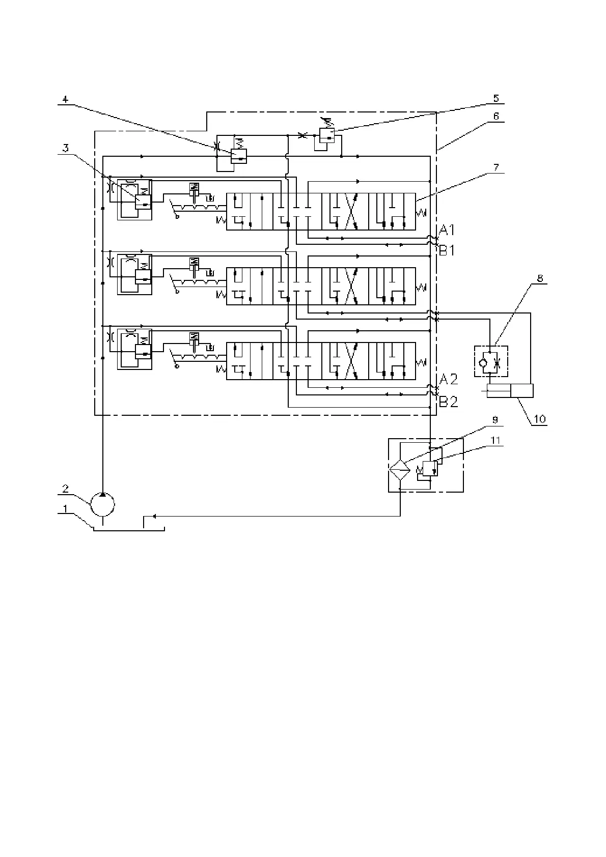
HLL hydraulic circuit diagram with the distributor Р80-3/1-222 installed is shown in
figure 3.15.8.
1 – HLL and HSC oil tank; 2 – HLL feed pump; 3 – valve of automatic return of the
spool; 4 – overflow valve; 5 – safety valve; 6 – distributor Р80-3/1-222-3Г; 7 – spool;
8 – retarding valve; 9 – filter; 10 – cylinder; 11 – filter valve.
Figure 3.15.8 – HLL hydraulic circuit diagram with the distributor Р80-3/1-222 in-
stalled