80-0000010B OM
175
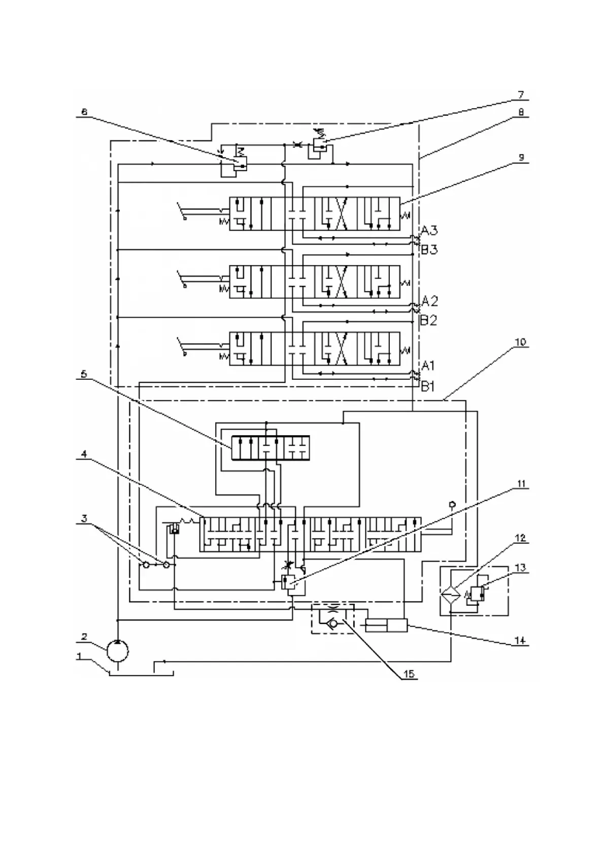
HLL hydraulic circuit diagram with the distributor Р80-3/4-111 is shown in figure
3.15.7.
1 – tank; 2 – pump; 3 – back-flow valve; 4 – sleeve; 5 – spool; 6 – overflow valve;
7 – safety valve; 8 – distributor Р80-3/4-111-3Гг; 9 – spool; 10 – draft (position) control;
11 – priority valve; 12 – filter of the hydraulic system; 13 – filter valve; 14 – cylinder; 15 – re-
tarding valve.
Figure 3.15.6 – HLL hydraulic circuit diagram with the distributor Р80-3/4-111 in-
stalled