80-0000010B OM
160
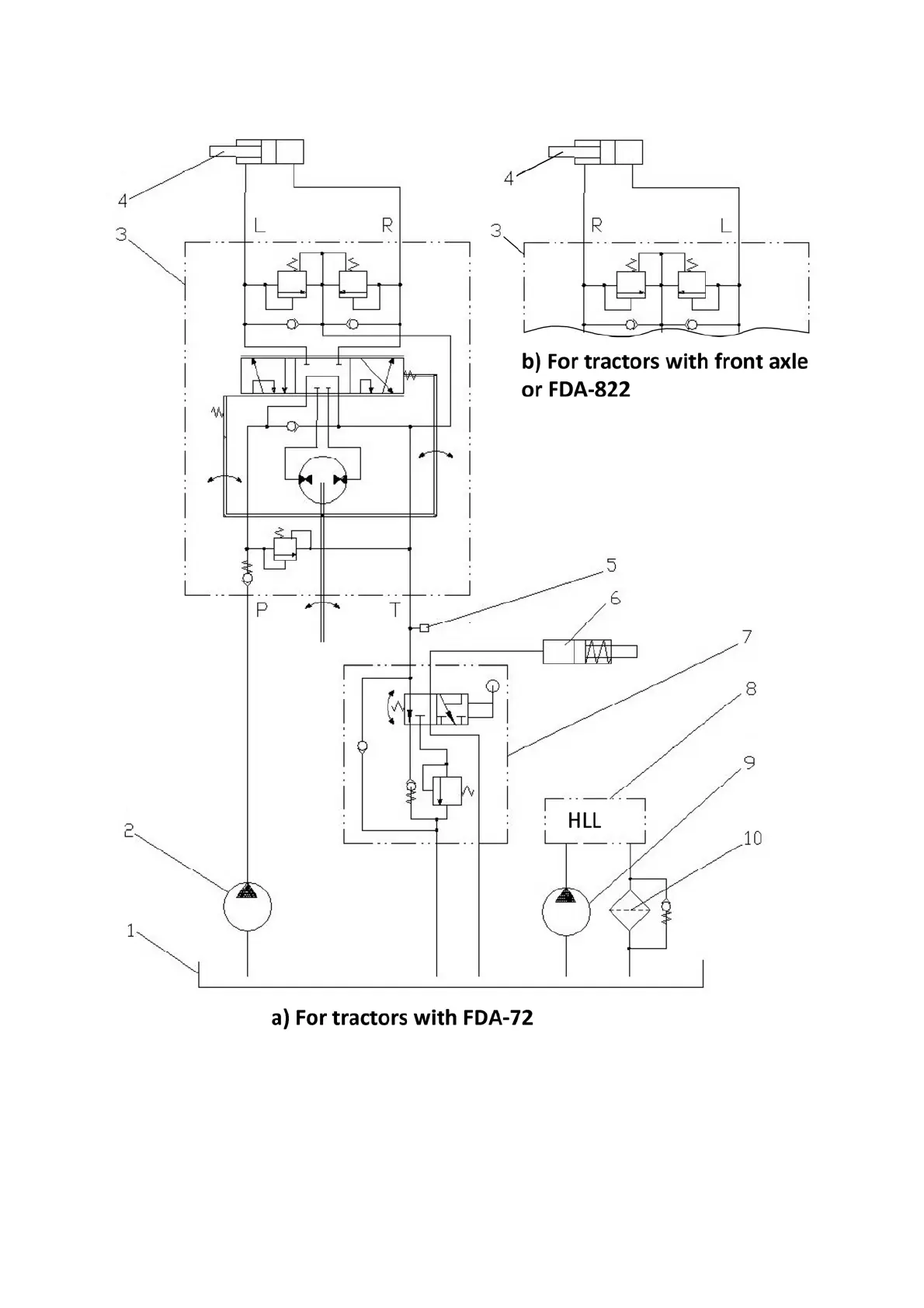
HSC hydraulic circuit diagram of tractors “BELARUS-80.1/82.1/820” is shown in fig-
ure 3.12.3.
1 – HLL and HSC combined oil tank; 2 – HSC feed pump; 3 – dosing pump;
4 – hydraulic cylinder of steering control; 5 – sensor of emergency oil pressure in HSC;
6 – differential lock coupling; 7 – rear axle differential lock valve (with pedal control);
8 – HLL hydraulic system; 9 – HLL pump; 10 – drain filter; Р – pressure hydraulic line; Т –
drain hydraulic line; L – left turn hydraulic line; R – right turn hydraulic line.
Figure 3.12.3 HSC hydraulic diagram of tractors “BELARUS-80.1/82.1/820” with dif-
ferential lock valve.