80-0000010B OM
140
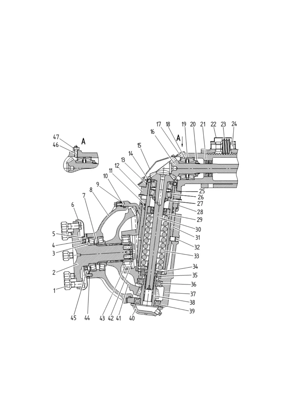
Sealing of the lower bevel gear and pinion is carried out by gasket 4 (figure 3.10.3),
ring 10 and shims over the sealing planes of wheel gear group 37 with cover 40 and gas-
ket body 5. To prevent dirt entry to working edges of gasket 4 dirt trap 6 is installed.
Brackets of front wheel fenders and brackets of steering trapezium 34 (figure
3.10.1) are attached to the wheel gear group housing.
Transmission of torque from differential axle shaft gear 1 (figure 3.10.2) to wheel
disc flange 2 (figure 3.10.3) with wheel attached to it is carried out by means of gears of
the upper and lower gears and pinions.
When turning the tractor force from the steering trapezium through steering rods and
swivel arms 34 (figure 3.10.1) is transmitted to the wheel gear groups housings, which turn
together with wheels relative to pivots tubes 26 (figure 3.10.3), in this case rolling of gears
of the upper and lower gear and pinion occurs.
1 – wheel mounting nut; 2 – flange; 3, 18 – tapered roller bearings; 4, 21, 29 – gaskets;
5 – gasket body; 6 – dirt trap; 7, 19 – adjusting rings; 8 – wheel gear group cover; 9, 25, 44 – ad-
justing shims; 10, 11, 13 – sealing rings; 12 – pivot tube flange; 14 – screw; 15 – cover; 16 –
half axle; 17 – upper gear and pinion housing; 20, 27 – nuts; 22 – cover; 23 – worm; 24 –
axle; 26 – pivot tube; 28 – seal housing; 30 – vertical shaft; 31 – pivot bush; 32 – pin; 33 –
spring; 34 – washer; 35 – thrust bearing; 36, 39 – ball bearing; 37 – wheel gear group hous-
ing; 38 – drive gear; 40 - cover; 41 – driven gear; 42 – washer; 43 – roller bearing; 45 –
bearing body; 46 – screw; 47 – lock nut.
Figure 3.10.3 – Bevel wheel gear group