80-0000010B OM
170
In the hydraulic lift linkage safety valve, retarding valve and filter valve have the following
intended use:
- safety valve, installed in the distributor, designated to prevent the HLL from overloading
by way of limiting the pressure in the range from 18 to 20 MPa (in case the pressure in the HLL
increases above the specified level, the oil flow is drained into the tank through the safety valve);
- retarding valve, installed directly in the cylinder, is designated to reduce lowering speed of
the mounted equipment to avoid damage to the working bodies by the ground.
- filter valve, installed in the filter body, is designated to limit drain pressure in the range
from 0,3 to 0,4 MPa (in case filter element is dirty oil flow through the filter valve is drained into
the tank bypassing the filter).
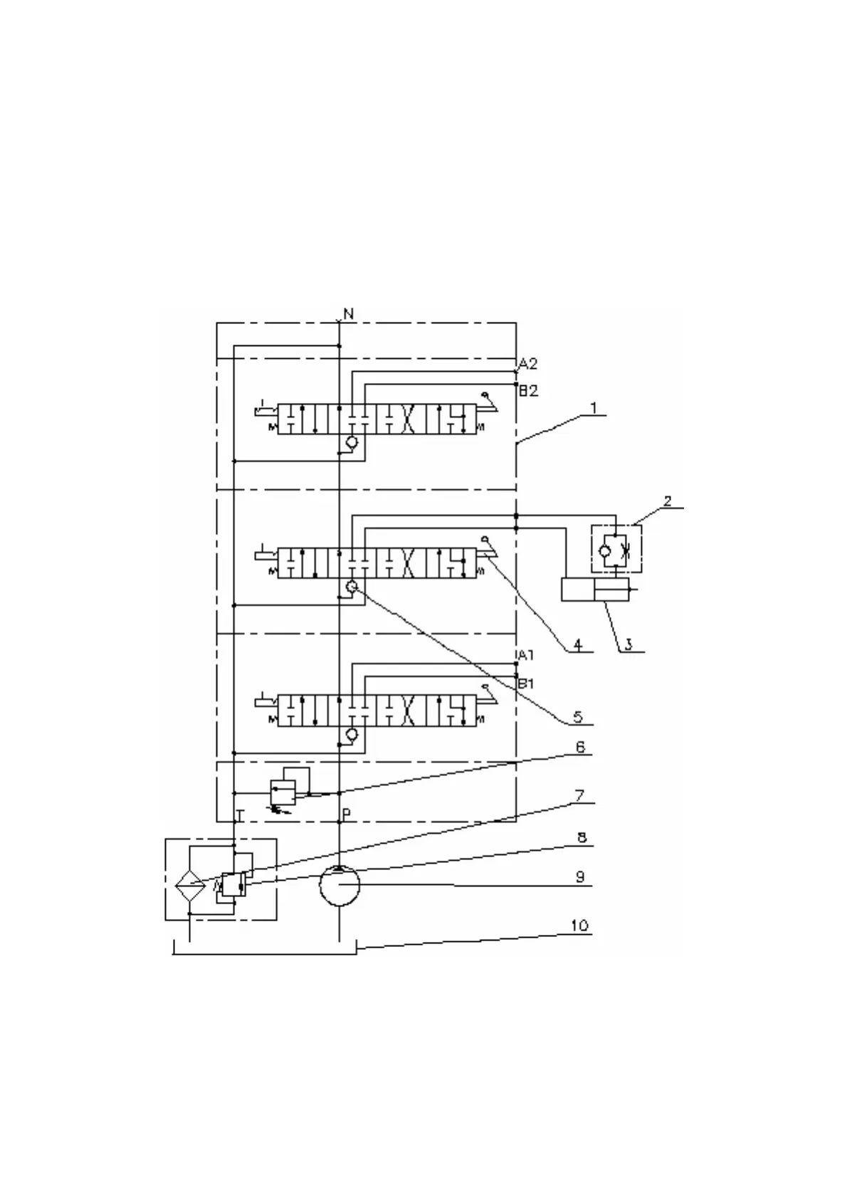
HLL hydraulic circuit diagram with the distributor
РП70-890 is shown in figure 3.15.2.
1 - distributor РП70-890.1, 2 – retarding valve, 3 - cylinder, 4 - spool, 5 – back-flow
valve, 6 – safety valve, 7 – hydraulic system filter, 8 – filter valve, 9 - pump, 10 - tank.
Figure 3.15.2 – HLL hydraulic circuit diagram with the distributor РП70-890.1 in-
stalled