80-0000010B OM
254
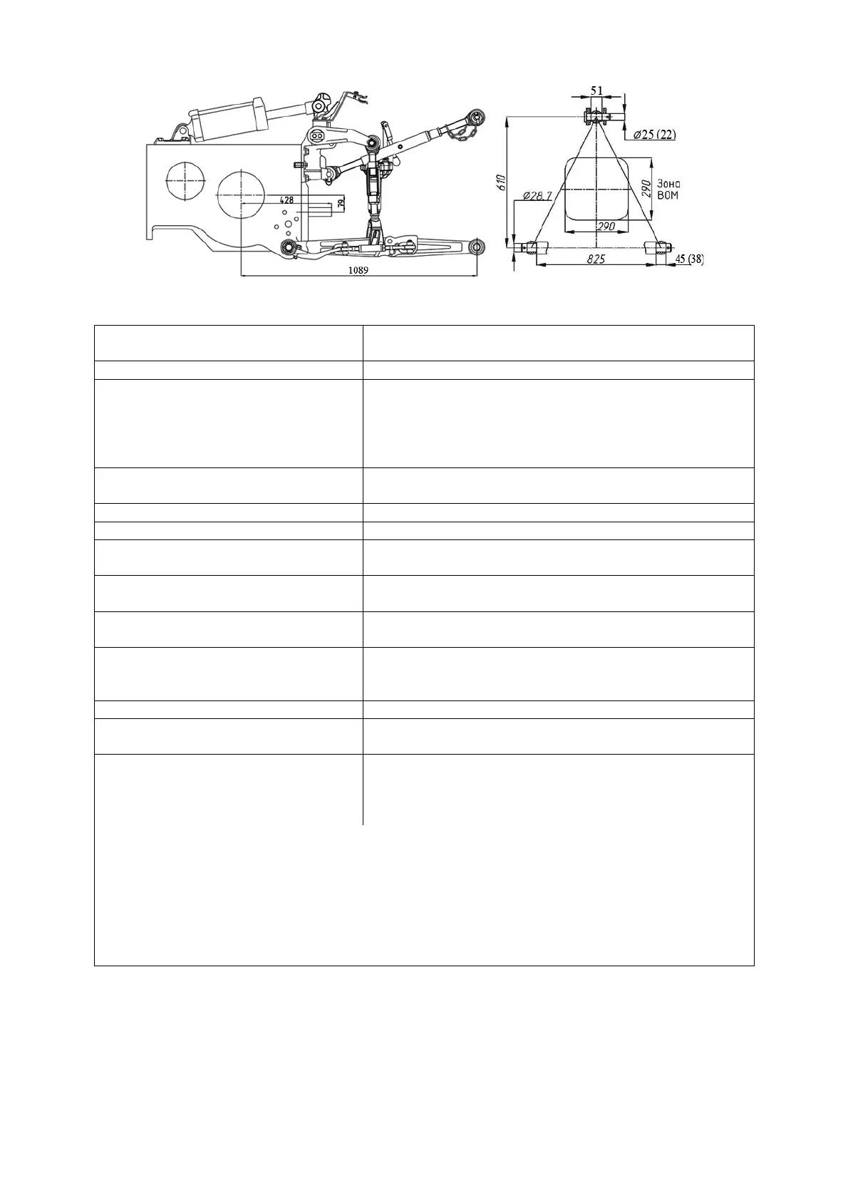
Figure 5.3.1 – Rear lift linkage diagram of type LL-2
Table 5.3.1 – Basic parameters and coupling dimensions of RLL
Standard size (configuration)
of the device
LL-2
Fi
ure 5.3.1
1 Cate
or
under ISO 730-1
Cate
or
2
2 Design features
Device consisting of three links (upper one and two
lower ones), pivot-connected with tractor;
free ends of links with hinge pivots are coupled dur-
ing implement coupling with the implement’s con-
nec
in
elements
3 Purpose To connect (mount) or couple agricultural mount-
ed, semi-mounted machines
4 Lower links Detachable, with hin
e pivots
optionall
: telescopic
5 Len
th of lower links, mm 885
6 Hinge pivots width of the upper
lower
link, mm
51 (45) under ISO 730-1
51
38
under GOST 10677
7 Diameter of a pin of a rea
-end
hin
e
ivot of the u
er link, mm
25 under ISO 730-1
22 under GOST 10677
8 Diameter of hole of rea
-end
hin
e
ivots of lower links, mm
28.7
9 Distance between PTO shaft
end extension face and suspen-
sion axis, mm
661
10 Column hei
ht
1)
, mm 610
11 Length of the suspension axis
alon
the shoulders
1)
, mm
825
12 Lifting power of the device, kN
2
:
a) on the suspension point;
b) on offset of 610 mm from sus-
ension
oin
30
18
_________________________________________________________________
_______________________________________________________
1)
Dimension refers to the implement coupled.
2)
It is not allowed to give RLL load exceeding loading of tyres specified by in-
structions set forth in subsection 4.2.8 ” Selecting of optimal inner pressure in tyres
depending on operational conditions and load on tractor axles, instructions for use of
t
res.”