80-0000010B OM
259
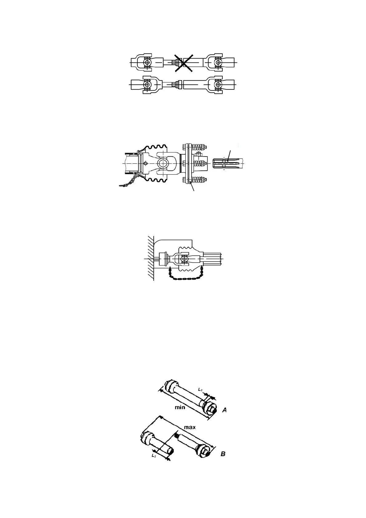
5. The implement cardan shaft end yokes from the side of PTO shaft and PRS shall
lie in the same plane as indicated in Figure 5.6.1.
Figure 5.6.1 – Cardan shaft mounting scheme
6. Safety clutch, as indicated in Figure 5.6.2, shall be installed only from the side of
PRS of the drive of the implement coupled; other methods of mounting will not ensure
timely protection of the tractor PTO shaft from excess of the maximum permissible torque.
After lengthy downtime check the implement safety clutch for technical condition.
Figure 5.6.2 – Safety clutch mounting scheme
7. Mounting of the cardan shaft with guard casing together with protective devices
of PTO shaft and PRS, with retaining chains both from the side of the PTO shaft and of the
PRS, as indicated in Figure 5.6.3, and ensures cardan joint safety.
Figure 5.6.3 – Scheme of safe cardan shaft mounting
8. When the cardan shaft is used for the first time it is necessary to check the car-
dan shaft length, and to adjust it to the operating conditions with tractors BELARUS-
80.1/82.1/820 when needed. For more detailed guidelines on cardan shafts see the tech-
nical documentation of the implement. Contact the cardan shaft manufacturer when need-
ed.
9. The length of the cardan shaft maximum driven apart, which is permitted for op-
eration, shall be of such type when one part of the cardan shaft enters the other for not
less than L
2
=150 mm. If the value is below L
2
=150 mm (Figure 5.6.4, view A) the cardan
shaft must not be operated. Sufficiency of overlapping L
2
can be checked by turning or lift-
ing of the implement coupled.
Figure 5.6.4 – Selecting the cardan shaft length
PRS
Safety clutch