!
Biodex Medical Systems, Inc. © 2016 19
Rear Panel
On the rear connector panel of the detector unit are two connectors. One is for power and data
communication with the display unit. The other is used to connect to a second detector. The
detector unit can be located up to 20 feet (6.09 meters) away from the display unit. The
standard cable measures eight feet (2.43 meters) in length.
Response
The response of this type of ionization detector has been carefully studied using radionuclides
calibrated at the National Institute of Standards & Technology. The result is a well-defined
energy response curve which is used to determine the calibration values for many different
isotopes with high accuracy. Each detector has been calibrated with a national institute of
standards & technology traceable source. The corresponding calibration value has been stored in
the memory of the detector unit. After calibration, the detector's accuracy is tested with
several sources of differing gamma energies whose activity values are traceable to the National
Institute of Standards & Technology.
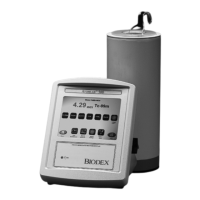
The Display Unit
The Atomlab 500 Dose Calibrator display unit consists of function keys and an LCD display that
allows you to make activity measurements. A built-in microprocessor executes commands input via
the touch panel and computes activity values from detector data.
The display unit, with a molded plastic case housing the electronics, has been specifically
designed to perform activity measurements in a laboratory setting. To allow easy fingertip control
of the button the front panel slopes gradually, providing an optimum viewing angle. On the rear
panel of the unit are the power and communication connectors, which remain out of the way as
they are infrequently adjusted.
Measurement Method
The current from the detector is measured in one of three ways, depending upon the order of
magnitude of the current. At low currents, the current from the detector is collected upon a
capacitor in the feedback loop of the electrometer whose capacitance is stable and measured to a
high degree. Voltage measurements are made upon this capacitor many thousands of times per
second. The time period between measurements is accurately calibrated. The second of two
successive values is subtracted from the first, which yields the net voltage change of the capacitor
over that short period of time. Thousands of successive differences are averaged over the course
of one second in order to determine the detector current during that second. After a sufficient
rise in voltage, the charge on the capacitor is emptied, reducing the charge and voltage by a
calibrated amount.
At medium currents, the capacitor will reach its maximum voltage value very quickly, and the
capacitor must be emptied quite often. At these currents, the number of times the capacitor is
emptied per unit time is used to calculate the current from the detector.
At high currents, the capacitor cannot be emptied fast enough. Instead, the switch which controls
when the capacitor is emptied is closed, and the electrometer is nulled. The value of The DAC
which is used to null the electrometer is used to determine the detector current at high currents.
During calibration, multiple measurements are made at current values at which two modes of
current measurement can be used effectively. These calibration measurements are used to set the
calibration parameters of the medium and high current modes so as to meet the linearity required
of the electrometer.