!
Biodex Medical Systems, Inc. © 2016 25
Power Up And System Test
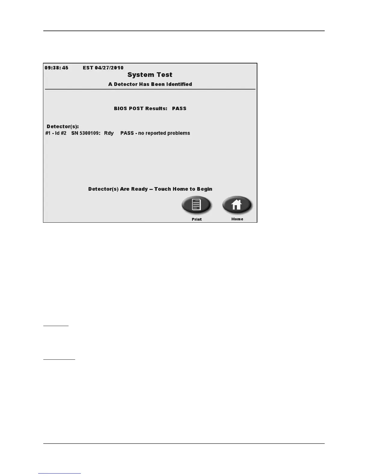
(See Figure 2.3.)
Figure 2.3. The Atomlab 500 System Test screen.
Connect the power cable to the back of the display unit and then plug the power supply into a
wall socket. Toggle the power switch, located on back of the display, to the “ON” (I) position. The
green power on led on the display will light and the system automatically performs a
background count and system-test as part of the power-up process.
NOTE: Be sure there is no source of activity in the detector, or nearby, which can cause the
initial background measurement to be incorrect.
The system test includes the following checks,
Display:
• CPU functions
• RAM memory (RAM diagnostics)
Detectors:
• Communication with all detectors
• High voltage readings to be in range
• All detector firmware checksums
• Validity of calibration factor values
• Background factor for an excessively negative or large value
• Detector memory integrity
• Electrometer failure status
• Detector gas pressure