!
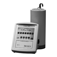
24 ATOMLAB 500 DOSE CALIBRATOR
1. Rotate the detector unit to access the connector on the base of the detector.
2. Insert one end of the RJ12 detector cable into the mating detector port.
3. Rotate the detector unit to its normal position so that the detector jack is facing away from
the work area.
NOTE: If you have more than one detector, use a second RJ-12 cable to connect the two
detectors in a serial fashion. It does not matter which RJ-12 port is used on a detector.
4. Rotate the display unit to access the connection ports located on the display back panel.
5. Insert the free end of the detector cable into the mating display port (there are two RJ-12
ports on the detector).
6. If you would like to connect a computer to the Atomlab 500, attach a null modem RS-232
Cable (or USB/RS-232 converter cable) with a DB9 connector to the computer serial port and
then attach the opposite end of the cable to the appropriate port on the display.
7. Insert the round end of the power supply or power pack into the power port on the display
unit.
8 Insert the female end of the power cord into the black, rectangular power pack. Turn the
display ON once the cord is plugged into the wall. The system will power-up and run a self-
test.
NOTE: As long as the Atomlab 500 is plugged in and power turned ON, the system will be
functioning. Depending on the Backlight Time setting, the display screen will eventually turn OFF.
Simply touch the screen to reactivate.
NOTE: If more than two USB ports are needed, a USB expansion hub (not included) can be used to
provide additional USB ports.
NOTE: The display can sit on the countertop or be mounted on the wall. Use the holes in the base to
mount to the wall.