P1 Patient Monitor User’s Manual
1-8
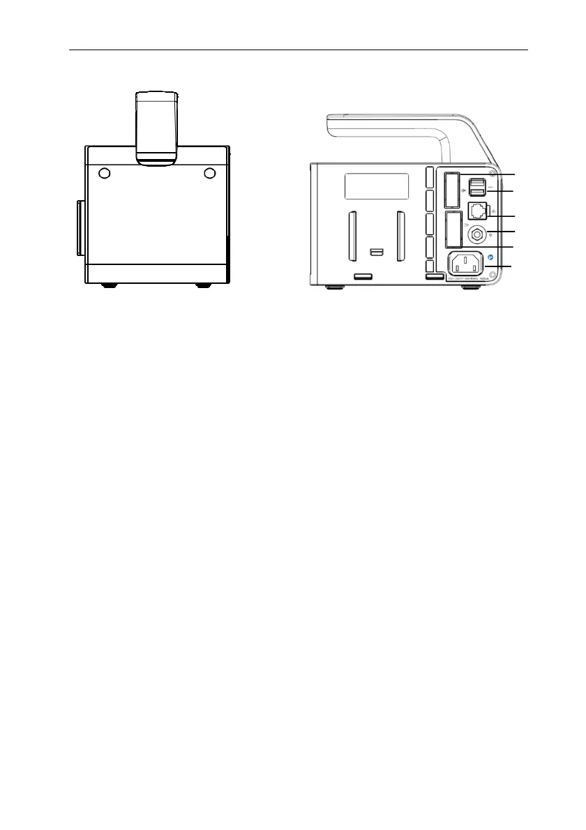
Right side Rear View
1. Handle
2. Plug-in module slots
3. Docking station connector: connects the P1 to the Docking Station.
4. Communication connector: connects the host monitor using cable.
5. USB connector: Connect to USB devices such as U disk, barcode scanner, mouse
and key board.
6. Network connector: The standard RJ45 interface, enabling networking with the
central monitoring system, other bed communications and system upgrades.
7. Equipotential grounding terminal
When other devices and monitors are unified used, the wires should be used to
connect the equipotential grounding terminal of other devices and monitors to eliminate
the potential difference between different devices and ensure safety.
8. VGA connector
Connect secondary display with a standard VGA connector. Auxiliary display and
monitoring are performed by connecting a secondary display. The display content of the
secondary display is consistent with the monitor display
9. AC power socket
4
5
6
7
8
9