info@biopac.com
support@biopac.com
www.biopac.com
BIOPAC Hardware | NIBP Systems | Page 2 - 8 Updated: 6.7.2013
SPECIFICATIONS
Cut-off Pressure Range: 100 – 300 mmHg (adjustable by 1mmHg steps)
Pressure Accuracy: 300 mmHg Full Scale 1%
Pressure Sensitivity: 0.1 mmHg
Pressure Signal output: 300 mmHg/3 Volt DC
Pulse Gain Levels: x1, x2, x4, x5, x8, x16, x32 (adjustable)
Pulse Signal Output: 0- 4 Volt DC
Pulse Display: Pulse intensity is displayed on A2, derived from plethysmographic measure The
tail sensor detects blood flow and pulse intensity is increased or decreased,
depending on the flow ratio.
LCD Display: 7” 800x480 TFT (NIBP250)
User Interface: Resistive Touch Panel (NIBP250)
Analog outputs: Two BNC connectors for uncalibrated pressure and pulse signals
Triggers: Two BNC connectors for TTL Compatible trigger in and out signals
Power Supply: 12 Volt 2 Amp – External
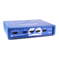
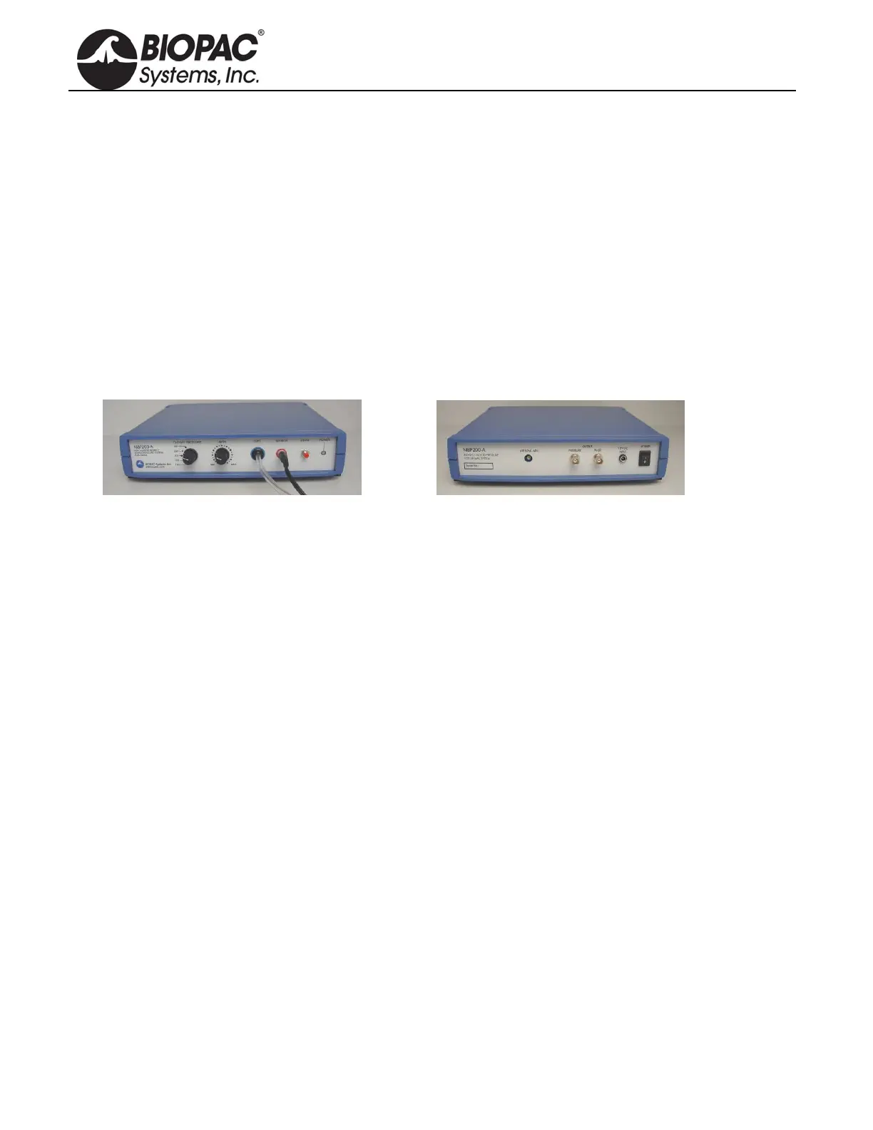
NIBP200A/NIBP250 SYSTEM CONNECTIONS
NIBP200A Front Panel NIBP200A Rear Panel
1. Connect the CBL150-Pre cable
a. BNC to the
PRESSURE output on the back panel of the unit.
b. Other end to A1 on the front of the UIM100C unit
2. Connect the CBL150-Pls cable
a. BNC to the
PULSE output on the back panel of the unit.
b. Other end to A2 on the front of the UIM100C unit.
3. Connect the IRSENSOR
a. Black cord to the sensor input on the front panel of the NIBP200A (back panel on NIBP250).
b. Tubing in the cuff on the front panel of the NIBP200A (back panel on NIBP250).
4. Connect the power
a. AC300 adapter to the 12V DC input on the back panel of the NIBP200A.
b. AC300 to Mains power.
5. Switch the POWER on.