info@biopac.com
support@biopac.com
www.biopac.com
BIOPAC Hardware | STIMULATORS MP3X | Page 5 - 9 Updated: 2.27.2013
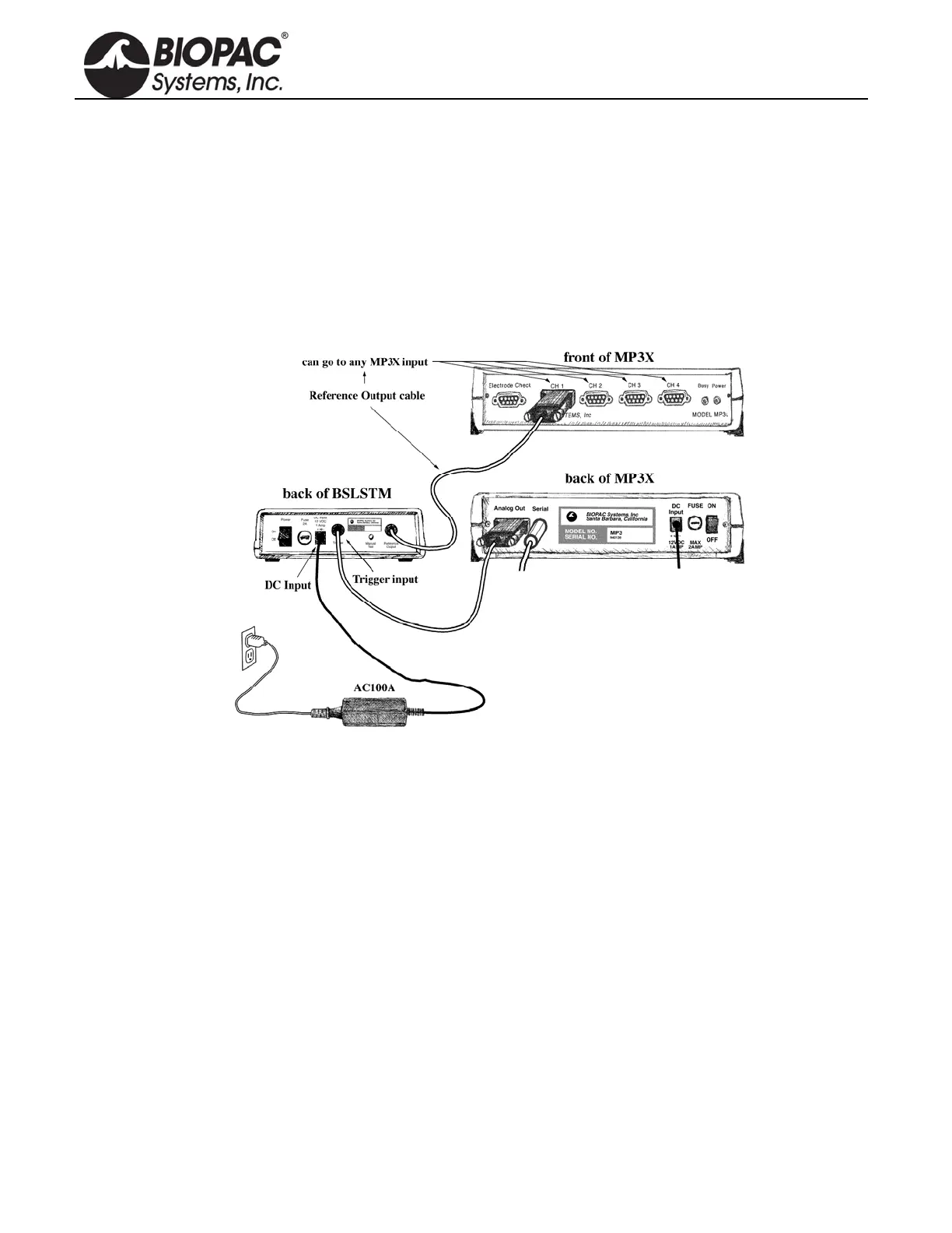
CONNECTING THE BSLSTM TO THE MP3X
1) Turn the MP3X unit OFF.
2) Confirm that Power switch on the back of the BSLSTM is in the OFF position.
3) Set the Range on the front of the BSLSTM to 0-10V.
4) Set the Level to 1 Volt.
BSLSTM: 1 Volt is set when the Major Scale (top number) is 1 and the Minor Scale (lower number)
is 0.
5) Plug the Trigger cable (female DB9 connector) from the back of the BSLSTM into the Analog Out port
(DB9 Male connector) on the back of the MP3X.
6) Plug the Reference Output cable (Male DB9 connector) from the back of the BSLSTM into an open
channel input port (DB9 female connectors: CH 1, CH 2, CH 3, or CH 4) on the front of the MP3X.
7) Plug the 12 Volt DC adapter into the wall.
8) Mate the DC output connector on the end of the adapter cable to the DC Input socket on the back of the
BSLSTM.
Make sure the connector is pressed in completely.
9) Plug the stimulator electrode assembly into the BNC connector on the front of the stimulator, labeled
Output on the BSLSTMA/B and Stimulus Output on the BSLSTM.
10) Place the BSLSTMA/B unit away from the MP3X. Placing the BSLSTMA/B too close to MP3X
hardware can result in data distortion of the BSLSTMA/B pulse width signal; the distortion is more
apparent at higher sampling rates.
NEVER set the BSLSTMA/B atop an MP3X.
Position the BSLSTMA/B away from the MP3X to reduce the signal distortion.