info@biopac.com
support@biopac.com
www.biopac.com
BIOPAC Hardware | Accelerometers | Page 2 - 3 Updated: 11.19.2013
IMPORTANT
Make sure the selected channel is not already assigned to any other BIOPAC module; up to 5
Accelerometers can be used with a single MP System. If contention exists, the channel data will
be corrupted.
See also: Setup notes for external devices and channel contention issues.
Software Setup
SS26LB/SS27L:
a) Select MP3X > Set Up Channels > Setup and enable three analog
channels, one for each axis
b) For each channel, select the appropriate Accelerometer Preset (5g or
50g) from the Preset list.
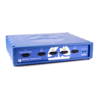
c) Click on Setup and then click on Scaling:
d) In the Scale value fields, enter the scaling factors required, 1 for Cal1
and –1 for Cal2.
e) Enter “g” for the Units label, as shown. (This unit should appear by
default in Accelerometer presets.)
f) Take the accelerometer and rest it in the upright position on the tabletop.
g) Calibrate the device by rotating it through 180° and taking a calibration reading at each point.
h) To calibrate the Y-axis, start with the transducer sitting on the table, face up, and click CAL1. Rotate the
transducer 180°, so that it is now sitting upside down, and click the CAL2 button. This procedure must be
followed for each axis. A label on the front of the transducer displays the X- and Y-axes. The Z-axis rotates
from the end with the label and the end with the cable.
TSD109 Series:
a) Select MP150 > Set Up Channels > Add New Module.
b) Choose HLT100C-A1 from the module type list and click “Add”.
c) Choose TSD109C (5g) or TSD109F (50g) from the transducer list and click “OK”.
d) Follow the onscreen calibration dialogs.
e) Repeat steps a-d for channels A2 (Y-Axis) and A3 (Z-axis).
Testing Calibration
To see if the calibration is correct:
a) Start acquiring data (for the test procedure, a sample rate of 50
samples per second should be used)
b) Rotate the accelerometer 180° through each axis.
c) Set the vertical scale to 1 and the midpoint to 0 for all channels.
d) Repeat the calibration procedure (by rotating the transducer 180°)
through each axis.
e) Visually confirm the correct calibration.
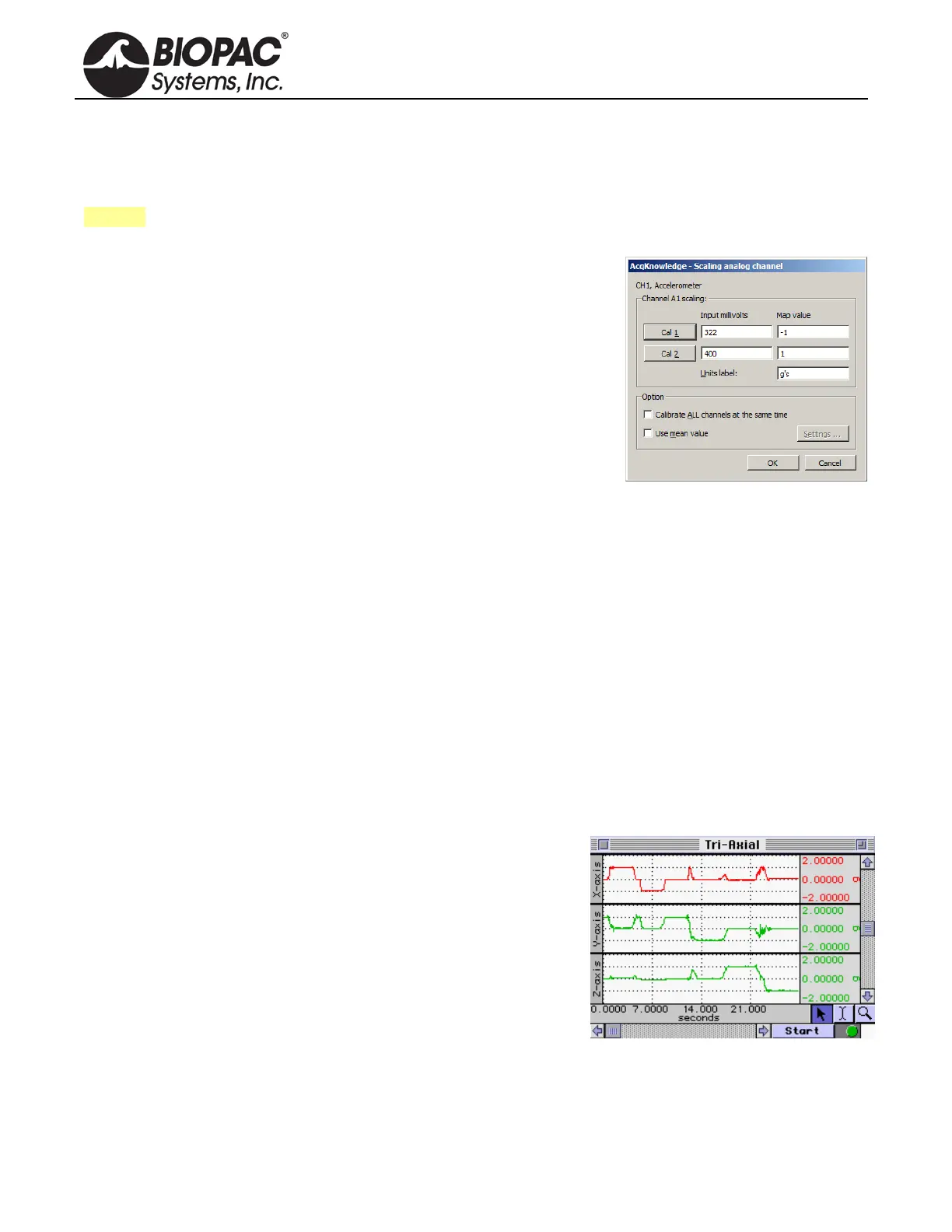
The screen shot above shows a tri-axial accelerometer being rotated through each axis. Channel 1 (X-axis) shows
the signal moving from 1g to -1g as the transducer is rotated. Likewise, Channel 2 (Y-axis) shows the same
phenomenon as previously described. Finally, Channel 3 (Z-axis) has also been tested and the
calibration confirmed.