info@biopac.com
support@biopac.com
www.biopac.com
BIOPAC Hardware | SS-KIT | Page 3 - 3 Updated: 3.28.2013
SS-KIT-OUT SPECIFICATIONS
PIN
LABEL
on PCB
PIN FUNCTION
MP36/MP35 MP30
1 AC_OUT Buffered analog or pulse output
A.C. coupled (1,000 uF)
Analog range: +/- 2.048 V
Pulse range: 0 to 2.048V
Buffered analog or pulse output
A.C. coupled (2,200 uF)
Analog range: +/- 2.5 V
Pulse range: 0 to 2.5V
2 DC_OUT Buffered analog or pulse output
D.C. coupled
Z out = 50
Range: 0 to 4.096 V
Buffered analog or pulse output
D.C. coupled
Z out = 50
Range: 0 to 5 V
3 GND Ground Ground
4 5V +5 V (100mA max.) +7.5 V (100 mA max.)
5 STR Buffered pulse output
Z out = 1 k
Range: 0 to 5 V
Un-buffered analog or pulse output (D.C.
coupled)
Z out = 1 k
Range: 0 to 5 V
6 12V +12 V (100 mA max) Not used
7 SCL
I
2
C SCL Do not connect!
Not used
8 SDA
I
2
C SDA Do not connect!
Not used
9 LIN
Monitor Do not connect!
Not Used
Notes Pins 1 and 2 For the MP36/MP35, pins 1 and 2 can output analog or pulses when using MP3X
firmware revision 1.26.037.030 or greater. When run under previous firmware, pins 1
and 2 can only be used for analog output. To identify the firmware revision, launch the
BSL PRO software and check the Help > About Biopac Student Lab dialog. See the
Support section at www.biopac.com
for upgrade information.
Pins 3, 4 and 6 The Power supply pins (3, 4 and 6) can be used for external circuits as long as the load
current does not exceed 100 mV.
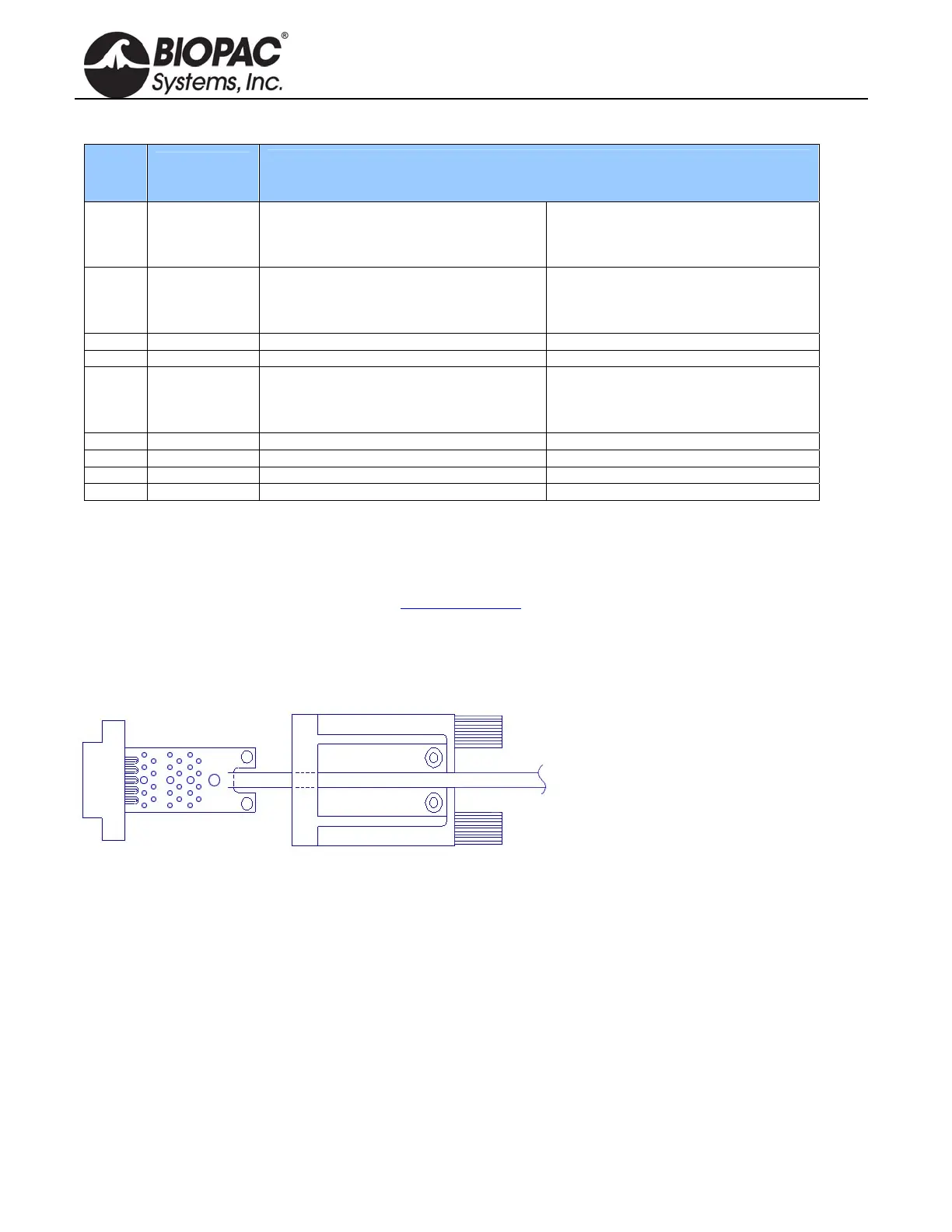
ASSEMBLY NOTES
The PCB assembly fits into the thumb
screw housing as shown. Two screws attach
the PCB to the housing and hold the strain
relief in place. The strain relief is used to
prevent the cable and attached wires from
pulling off th
e SS-KIT-OUT PCB. It is a
good idea to place the strain relief over the
cable prior to soldering the wires to the
PCB so that it only has to be slid on a small distance. If the strain relief fits too tightly around the cable, use water
to wet the cable, allowing the strain relief to slide. Place the strain relief such that the case cover pinches and
holds the cable. The stick on panel is used to cover the screws and protect the label.