info@biopac.com
support@biopac.com
www.biopac.com
BIOPAC Hardware | SS-KIT | Page 1 - 3 Updated: 3.28.2013
See also: TCI series of available interfaces
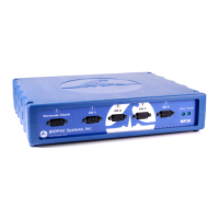
SS-KIT-IN TRANSDUCER CONNECTOR INTERFACE KIT - INPUT
This kit is for users who wish to adapt their own transducers to the Biopac
Student Lab PRO System. The kit comes with a Smart Sensor connector,
cable and components to properly interface with the transducers. The kit
will allow quarter, half or full bridge transducers (pressure, force, strain,
acceleration, sound, etc.) to
be connected to the system.
SS-KIT-IN COMMENT
S AND SUGGESTIONS
1) Be careful of consumption.
The bridge circuit should be designed so no more than
5mA are used to power the bridge. If the bridge takes
mor
e than 5mA, try reducing the voltage across the
bridge by using series resistors or other kinds of
regulators.
2) Be careful of signal amplitude.
The signal input (conditioned by the bridge) should
provide a signal no greater than ±50 mV between pins 2
and 4 on the 9 Pin D Male connector. If this voltage
exceeds 50 mV (of either polarity), the input amplifier
stages will saturate.
PIN Description
1 Shield
2 Vin+
3 Ground
4 Vin-
5 Shield
6 +5 volts (ref)
7 No Connection
8 No Connection
9 -5 volts (ref)
9 Pin D Male connector pin-outs
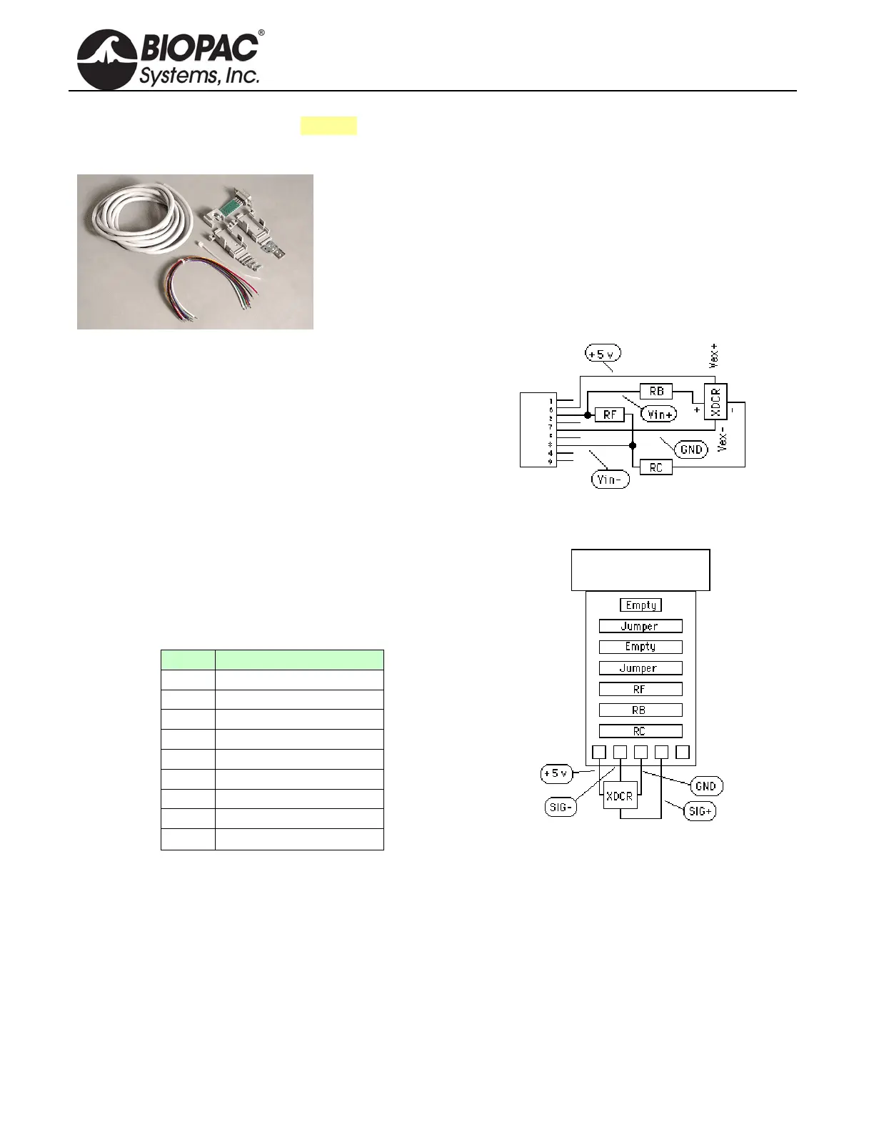
Schematic
Printed circuit board layout