info@biopac.com
support@biopac.com
www.biopac.com
BIOPAC Hardware | SS11LA & TSD117 | Page 2 - 7 Updated: 12.2.2013
Use the following measurement procedure for determining lung volume:
1. Breathe normally for 3 cycles (start on inspire)
2. Inspire as deeply as possible
3. Return to normal breathing for 3 cycles
4. Expire as deeply as possible
5. Return to normal breathing (end on expire)
Data Processing
When integrating the colle
cted data to determine lung volume, it’s important to integrate fro
m the starting point of
the first inspire, to the end point of the last expire. Before integration, the mean of the selected (airflow) data must
be determined and then subtracted from the record. This process insures that the integral will have the same
starting and ending point.
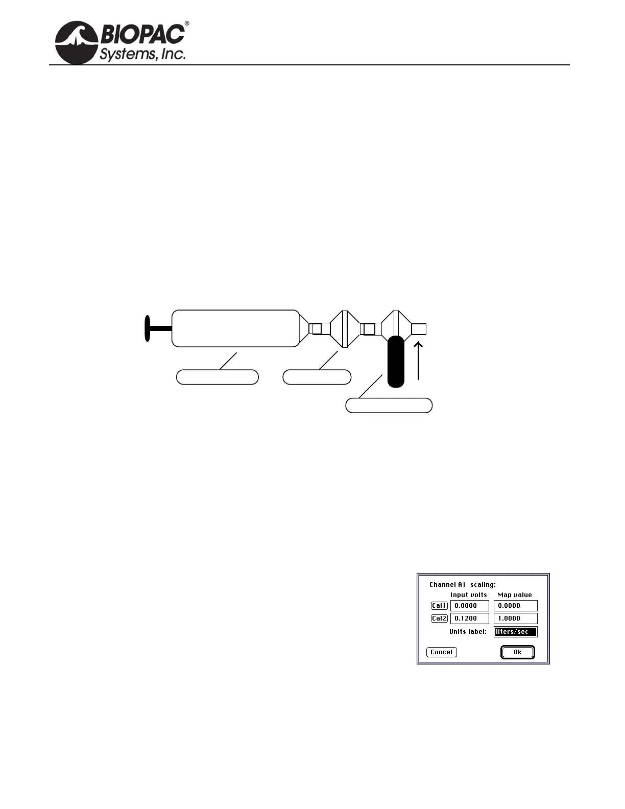
Calibration For Medium-Flow Pneumotachs
1. Syringe Calibration
Calibration Syringe
Air Flow Transducer
Vertical
Orientation
Bacterial Filter
After the calibration process, please remove the calibration syringe and attach a new bacterial filter and
mouthpiece to the airflow transducer.
It’s very important that each individual use his/her own mouthpiece and bacterial filter.
Place the narrow end of the bacterial filter and mouthpiece assembly into either side of the airflow transducer.
Airflow data can now be recorded. For best results, hold the airflow transducer vertically.
2. Mathematical Calibration
The transducer can be roughly calibrated without using the calibration syrin
ge. Using the transducer’s nominal
output of 60µV per liter/sec (normalized to 1 volt excitation), the following calibration factors can be entered in
the software Scaling window.
Scaling Factors for Rough Calibration of the airflow transducer
The following equation illustrates why 0.12 volts maps to 1.00 lite
r/sec:
Calibration Constant • Amp Gain • Amp Excitation = Scale Factor
Thus
60 µV/[liter/sec] • 1000 • 2 Volts = 0.12 V / [liter/sec]
Data can now be collected directly. Prior to analyzing the data, remember that there will always be some offset
recorded in the case of zero flow.
Note: With the TSD117 and MP150/100 system, it’s possible to largely trim this offset out, using the ZERO
potentiometer on the DA100 amplifier, but some residual will always remain.