info@biopac.com
support@biopac.com
www.biopac.com
BIOPAC Hardware | MP36/35/45 | Page 6 - 11 Updated: 12.23.2013
MP Unit Pin-outs
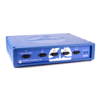
Electrode Check — MP36/35 Front
9-PIN FEMALE DSUB
Pin
2 Vin+ Electrode connection
3 GND
4 Vin- Electrode connection
MP Input — Front
CH 1, CH 2, CH 3, CH 4
9 PIN FEMALE DSUB
(1 of 4 for MP36/35 or 1 of 2 for MP45)
Pin MP36 and MP35 or MP45
1 Shield drive Shield drive
2 Vin+ Vin+
3 GND GND
4 Vin Vin
5 Shield drive Shield drive
6 +5 V (100 mA max aggregate) +5 V (50 mA max)
7 ID resistor lead 1; I2C SCL ID resistor lead 1 (+5 V)
8 ID resistor lead 2; I2C SDA ID resistor lead 2
9 5 V (100 mA max aggregate) 5 V (50 mA max)
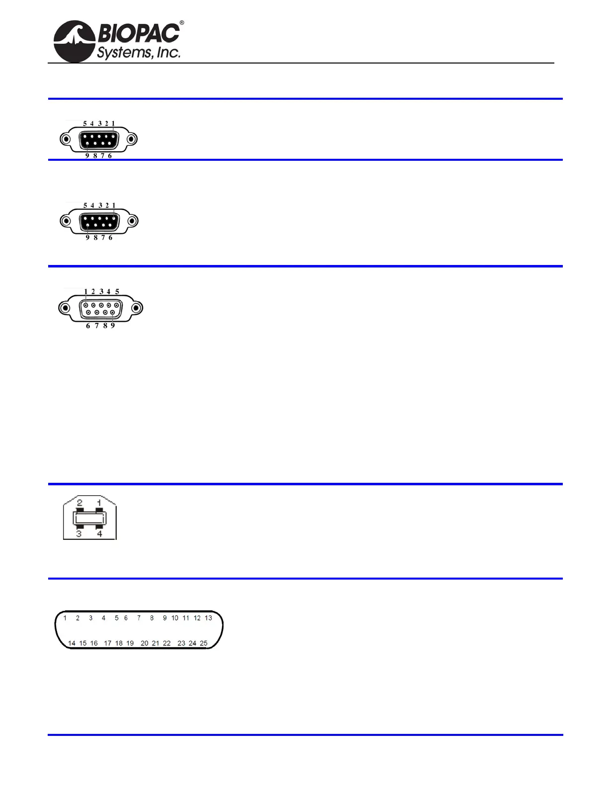
MP Analog Output — MP36/35 Back
9 PIN MALE DSUB
Pin MP36 and MP35
1 Buffered analog or pulse output
A.C. coupled (1,000 uF)
Analog range: +/- 2.048 V
Pulse range: 0 to 2.048 V
2 MP36 Low voltage stimulator
MP35 Pulse or CH data
Buffered, D.C. coupled
Z out = 50 Ω
Range: MP36 -10 V to +10 V
MP35 0 V to +4.096 V
3 GND
4 +5 V (100mA max.)
5 Buffered pulse output
Z out = 1 kΩ
Range: 0 to 5 V
6 +12 V (100 mA max)
7 I2C SCL – Do not connect
8 I2C SDA
9 Monitor – Do not connect
Connector — Back
MP36/35
Pin MP36 or MP35
1 +5 N/C
2 -Data clock
3 Data + RX+
4 GND Ground
5 n/a TX-
6 n/a RX-
7 n/a N/C
8 n/a TX+
MP UNIT PIN OUTS continued
I/O Port — MP36 or MP35 Back
DSUB 25 (male)
Note: BSL v 3.7.0 does not support
Pins 7, 9, 18, 19, 20 and 21.
† Digital Input are 0-5 V with 100 K ohm
pullups to 5 V on board
Pin MP36 or MP35 only
1 Digital Output 1 0-5 V 8 ma 14 Digital Output 5
2 Digital Output 2 0-5 V 8 ma 15 Digital Output 6
3 Digital Output 3 0-5 V 8 ma 16 Digital Output 7
4 Digital Output 4 0-5 V 8 ma 17 Digital Output 8
5 GND Unisolated 18 Analog Input, Right
6 GND Unisolated 1 VRMS, centered at 0 V
7 RS-232-RX 19 Analog Input, Left
8 +5 V Unisolated/fused 1 VRMS, centered at 0 V
9 I2C-SDA 3.3. V 20 RS-232-TX 0-5 V
10 Digital Input 1† 0-5 V 21 I2C-SCL 3.3 V
11 Digital Input 2† 0-5 V 22 Digital Input 5
12 Digital Input 3† 0-5 V 23 Digital Input 6
13 Digital Input 4† 0-5 V 24 Digital Input 7
25 Digital Input 8