info@biopac.com
support@biopac.com
www.biopac.com
BIOPAC Hardware | MP36/35/45 | Page 3 - 11 Updated: 12.23.2013
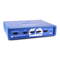
Back Panel
Back Panel, MP36/35
The back panel of the MP36/35 has an analog output port, a USB port, an I/O Port, a Trigger Port, a DC input, a
fuse holder, a power switch, and the unit’s serial number.
The back panel of the MP45 has a USB cable and headphone port.
Analog Out Port – Low Voltage Stimulator
There is one 9-pin m
ale “D” analog output po
rt on the back of the MP36/35 that allows signals to be amplified
and sent out to devices such as headphones. On the MP36, Analog Out is built-in low voltage stimulator.
Not available for MP45.
USB Connection
The MP36/35 connects to the computer via a USB Port, located just below the word USB.
Uses a standard USB connector.
Should only be used to connect the MP36/35 to a PC or Macintosh.
The MP45 USB cable is a full-speed USB connector and should only be used to connect the MP45 to a
PC or Mac USB port.
Headphone Output
Accepts a standard (1/4” or 6.3mm) stereo headphone jack; functional for MP36 and MP45 only.
I/O Port (MP36/35 only)
Accepts
a DB 25 Female
connector.
Input/Output port used to connect digital devices to the MP36/35.
Trigger Input (MP36/35 only)
Accepts a male BNC connector.
Input
port used to send trigger signals from another device to the MP36/35.
MP system external trigger inputs are TTL compatible—this means that one needs to send the external
trigger input 0 volts for a TTL low and 5 volts for a TTL high.
The external trigger inputs are equipped with internal pull-up resistors—this means that they
automatically sit at TTL high, if left unattached.
This is a common and helpful implementation, because all one requires to implement an external
trigger is to pull the external trigger input low.
This implementation is typically performed with an external switch placed between the external
trigger input and ground.
When the switch is closed the external trigger input is pulled to TTL low.
When the switch is opened the external trigger input is pulled back (by the internal pull-
up resistor) to TTL high.