info@biopac.com
support@biopac.com
www.biopac.com
BIOPAC Hardware | Gonio-Torsio | Page 2 - 9
Updated: 11.21.2013
ATTACHMENT TO THE SUBJECT
Various combinations of display and recording instrumentation have been carefully developed fulfilling the requirements
of specific research applications. Due to the wide range of applications, one method of attachment cannot be
recommended. Experience has proven that standard medical adhesive tape is an excellent adhesion method in the majority
of cases. Single-sided and double-sided medical tape (such as BIOPAC TAPE1 or TAPE2) should be used for the best
results.
1. Attach pieces of double-sided tape to the underside of the goniometer endblocks.
2. Stick the tape to the subject and allow for the telescoping of the goniometer. The goniometer should be fully
extended when the joint is fully flexed.
3. Press the two endblocks firmly onto the subject and ensure that the goniometer is lying over the top of the
joint. When the joint is extended, the goniometer may present an “oxbow.”
4. For additional security, pass a single wrap of single-sided medical tape around each endblock.
5. Secure the cable and connector leaving the goniometer with tape to ensure that they do not pull and detach the
goniometer.
For accurate results from long recordings
Employ double-sided adhesive between the endblocks and skin, and place single-sided adhesive tape over the top of the
endblocks. No tape should come into contact with the spring. The connection lead should also be taped down near the
goniometer.
For applications where quick or rapid movements are involved
Fit a “sock” bandage over the whole sensor and interconnect lead. This does not apply to the finger goniometer
(TSD130E/SS24L/SS24/BN-GON-F-XDCR), which has a different working mechanism.
When the goniometer is mounted across the joint, the center of rotation of the sensor measuring element may not coincide
with the center of rotation of the joint (for example, when measuring flexion /extension of the wrist). As the joint moves
through a determined angle, the relative linear distance between the two mounting positions will change.
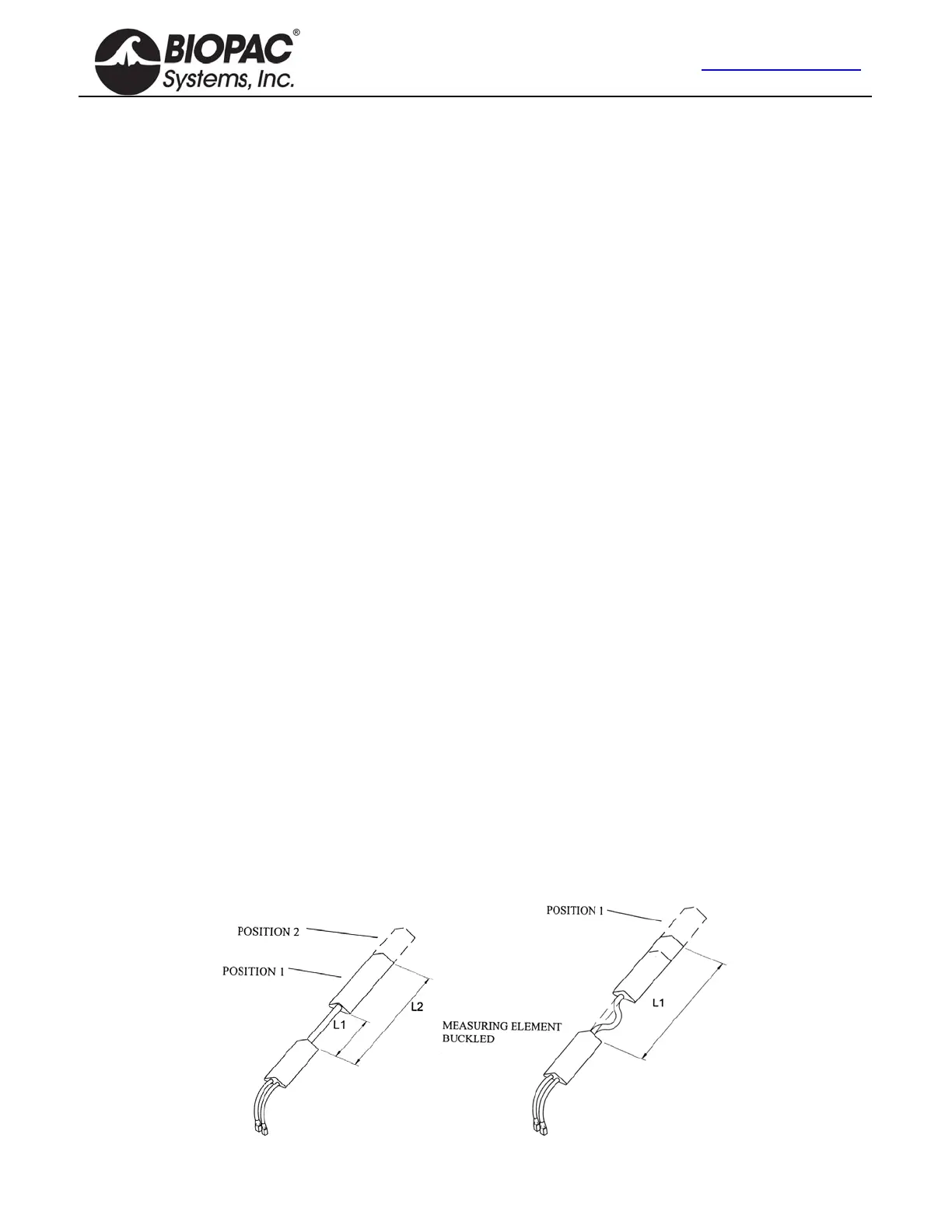
To compensate for this, all sensors are fitted with a telescopic endblock that permits changes in linear displacement
between the two endblocks along axis ZZ without the measuring element becoming over-stretched or buckled.
In the free or unstretched position, the distance between the two endblocks is L1.
If a light force is applied, pushing the endblocks away from each other, this length will increase to a maximum of L2.
When the light force is removed, the distance between the two endblocks will automatically return to L1.
This creates several advantages: accuracy is improved; sensors can be worn comfortably and undetected under normal
clothing; the tendency for the position of the sensors to move relative to the underlying skeletal structure is reduced.