info@biopac.com
support@biopac.com
www.biopac.com
BIOPAC Hardware | MP36/35/45 | Page 2 - 11 Updated: 12.23.2013
Transducers,
on the ot
her h
a
nd, convert
a physical signal into a proportional electrical signal.
Input/Output devices (I/O for short) are specialized devices like pushbutton switches and headphones.
Simple Sensor Connectors
Regardless of
the type of device connect
ed, every sensor or I/O device connects to the MP36/35 using a “Simple
Sensor” connector. Simple Sensor connectors are designed to plug only one way into the MP unit—no need to
worry about plugging things in upside down or into the wrong socket!
Electrodes, transducers, and the pushbutton switch all connect to the channel input ports on the front
panel of the MP36/35 and MP45.
Headphones and the stimulator connect to the “Analog out” port on the back panel of the MP36/35 and to
the headphone jack on the top of the MP45.
MP36/35 only: A digital device may connect to the “I/O Port” on the back panel
MP36/35 only: A trigger device may be connected to the “Trigger” port on the back panel.
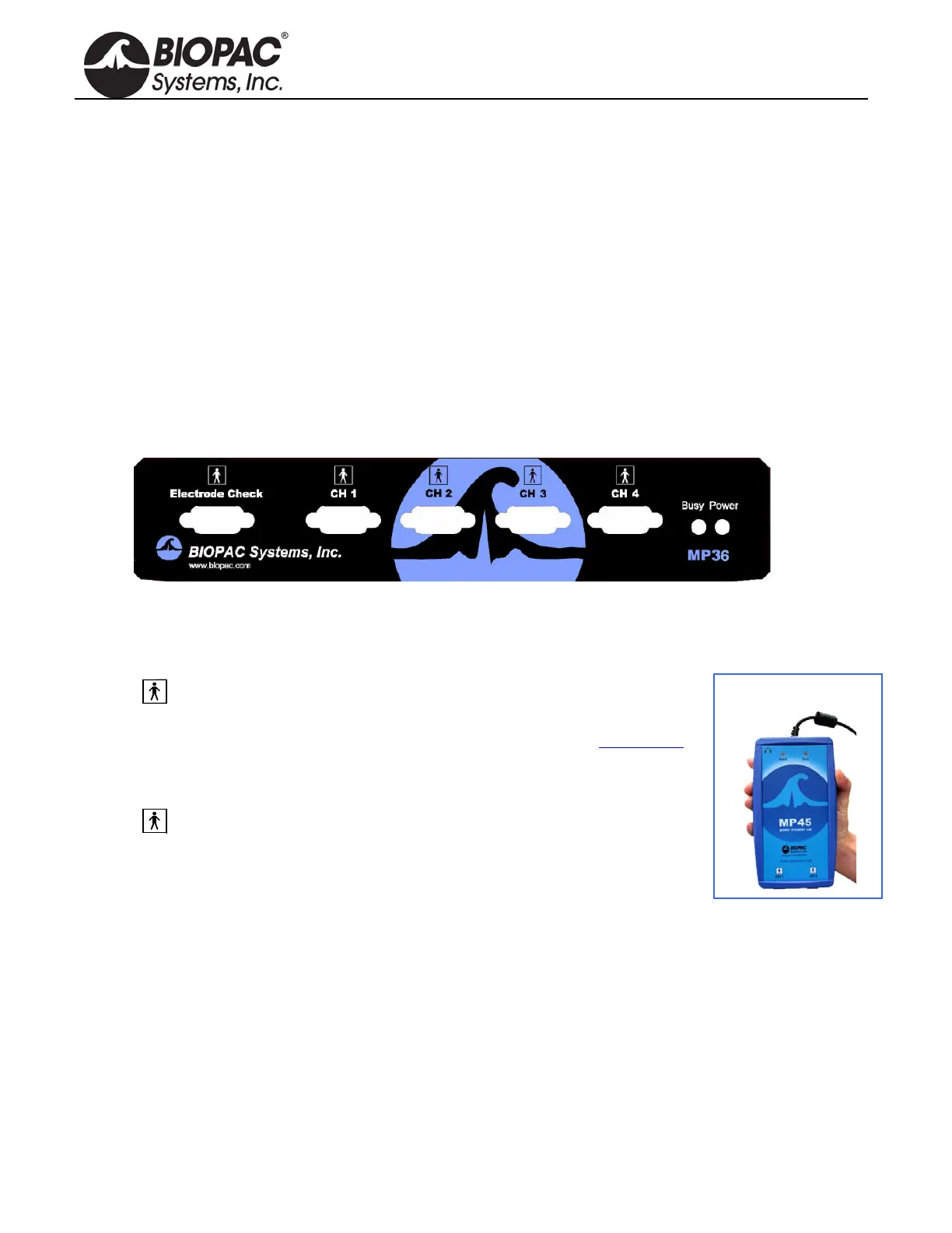
Front Panel
Front Panel, MP36/35
The front panel of the MP36/35 has an electrode check port, four analog input ports, and two status indicators.
Electrode Check
The Electrode Check port is a diagnostic tool used with the BSL PRO
software to determine if the electrodes are properly attached to the subject.
The MP45 does not have an Electrode Check port. Use BIOPAC’s EL-CHECK
standalone electrode impedance checker to measure electrode/skin contact.
MP45 is
CH 1 and CH 2 only.
Input Ports: CH 1, CH 2, CH 3, and CH 4
The 9-pin female analog input ports on the MP acquisition unit are referred
to as Channels. There are four on the front of MP36/35 Units and two on the
MP45. The Biopac Student Lab Lessons software will always check to see that
the proper sensors are connected to the appropriate channel.
Status Indicators
Busy—indicator is activated when the MP36/35 is acquiring data and also during
the first few seconds
after the MP36/35 is powered on to indicate that a self-test is in progress. (When the MP36/35 passes the
power-on test, the Busy light will turn off.)
Power—status indicator is illuminated when the MP36/35 is turned on.
Ready—status indicator is illuminated when the MP45 is plugged in and communicating.