info@biopac.com
support@biopac.com
www.biopac.com
BIOPAC Hardware | NIBP Systems | Page 5 - 8 Updated: 6.7.2013
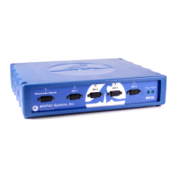
Input volts Scale (Map) value
Cal 1
0 0
Cal 2
1 100
Units Label:
mmHg
The scaling must be adjusted as the cut-off
pressure switch settings are changed. If the
pressure switch is set to 300 mmHg, then the
settings should be:
Input volts Scale (Map) value
Cal 1
0 0
Cal 2
3 300
Units Label:
mmHg
b. Click OK as needed to close out of A1 setup.
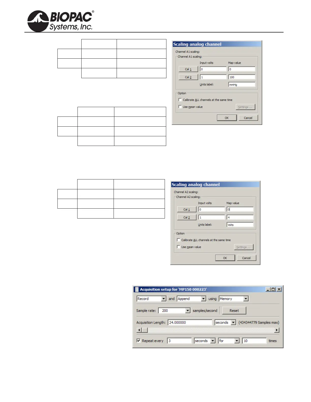
5. Calibrate for the pulse measurement of IRSENSOR.
a. Ensure that the tail is not inside the IRSENSOR and it is empty, and the sensor resides freely.
b. Select A2 (Pulse) and click Setup and establish these settings:
Input volts Scale (Map) value
Cal 1
0 0
Cal 2
1 4
Units Label:
Volts
c. Click OK as needed to close out of A2 setup and the Setup Channels dialog.
6. Choose MP menu > Set up Acquisition and establish the following settings.
Mode = Record and Append to
Memory
Sample Rate = 200
samples/second
Total Length = 24 seconds
Repeat = every 3 seconds for 10
times
7. Close out of Set up Acquisition.
8. Choose MP menu > Setup Trigger and establish the following settings.