Using External ATEM Hardware Panels
Menu Buttons
The matrix of menu buttons are organized into a multi level tree structure of pages that are very
easy to navigate. To assist in rapid navigation all menu pages have a HOME button at the
bottom right and most operations only require navigating down one level.
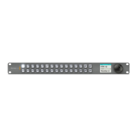
Joystick and Numeric Keypad
The Number Pad is used to enter numerical data. For example, when setting the transition rate
of a transition, the number pad can be used to enter a numerical value for the transition
duration. When entering data using the number pad, the soft buttons below each parameter
are used to apply the entered data to that parameter.
The Joystick is a 3-axis joystick that is used to size and position keys, DVEs and other elements.
Joystick Control
Controlling Cameras using the Joystick
The joystick can also be used to control a remote camera head using the common VISCA
protocol when connected to an ATEM 1 M/E or 2 M/E model switcher. This is an extremely
powerful tool for controlling pan, tilt and zoom on remote cameras, also known as PTZ control.
You can easily control a bank of cameras one at a time by selecting each camera using the
system control soft buttons, then making your adjustments with the joystick.
You can also choose the tilt direction of your joystick by pressing the PTZ soft button on the
panel, which will give you the options of ‘normal’ or ‘inverted’ to select from. Selecting ‘inverted’
will reverse the tilt action of your joystick.
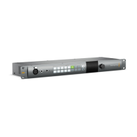
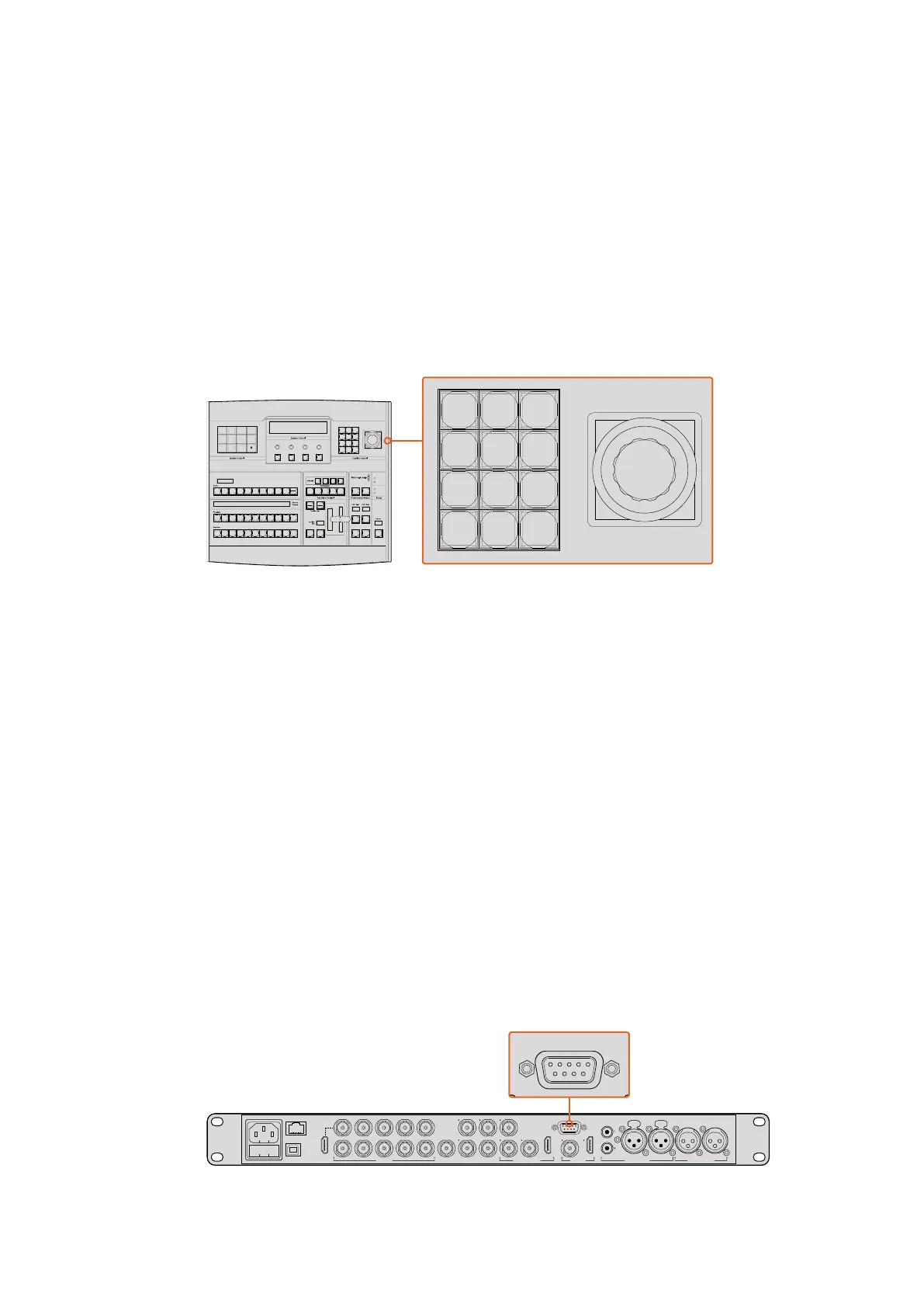
Connecting a Remote Head
Your ATEM Broadcast Panel communicates with remote heads via your ATEM switcher’s RS-422
port labeled ‘remote’ or ‘RS-422 serial out’. After connecting your ATEM Broadcast Panel to
your ATEM switcher via Ethernet, simply connect your ATEM switcher to the RS-422 input on
the remote camera head. RS-422 ports are typically DB-9 serial ports, or RJ11 connectors that
look similar to a standard landline phone connector.
You’ll also need to make sure the remote behavior for your switcher’s RS-422 port is set to
‘PTZ’ in the ATEM Software Control general settings.
When connecting more than one remote head, they will normally be daisy chained together via
the RS-422 outputs/inputs between each head.
Connect a remote camera head to your ATEM 1 M/E or 2 M/E model
switcher via the RS-422 port labeled ‘remote’ on the rear panel.
CUT
SHIFT
ON
KEY 1
KEY
1
KEY
2
KEY
3
KEY
4
PATTRN
KEY
CHROMA
KEY
LUMA
KEY
MASK
MENU
HOME
DVE
BKGD
CUT AUTO
KEY 2 KEY 3 KEY 4
ON ON ON
1 2 3
4 5 6
7 8 9
CAM 0 CLR
PREV
TRANS
FILL
DIP
MIX
DVE
WIPE
DSK 1
TIE
DSK 2
Control Panel
Switcher
Main
Backup
Main
Backup
TIE
DSK 1
CUT
DSK 2
CUT
DSK 1
AUTO
DSK 2
AUTO
FTB
CUT
SHIFT
ON
KEY 1
KEY
1
KEY
2
KEY
3
KEY
4
PATTRN
KEY
CHROMA
KEY
LUMA
KEY
MASK
MENU
HOME
DVE
BKGD
CUT AUTO
KEY 2 KEY 3 KEY 4
ON ON ON
1 2 3
4 5 6
7 8 9
CAM 0 CLR
PREV
TRANS
FILL
DIP
MIX
DVE
WIPE
DSK 1
TIE
DSK 2
Control Panel
Switcher
Main
Backup
Main
Backup
TIE
DSK 1
CUT
DSK 2
CUT
DSK 1
AUTO
DSK 2
AUTO
FTB
PUSH PUSH
CONTROL
USB 2.0 HDMI IN
SDI INPUTS REF IN AUX 1-3 PREVIEW PROGRAM OUTPUTS MULTI-VIEW ANALOG AUDIO IN
STEREO IN
REMOTE
ANALOG AUDIO OUT
CH 1
All SDI and HDMI video connections are
SD, HD and Ultra HD switchable unless indicated
CH 2CH 1 CH 2
IN
1
IN
2
IN
1
IN
3
IN
4
IN
5
IN
6
IN
7
IN
8
IN
9
IN
10
2
1 3
2
1
HD HD HD
184
 Loading...