Using External ATEM Hardware Panels
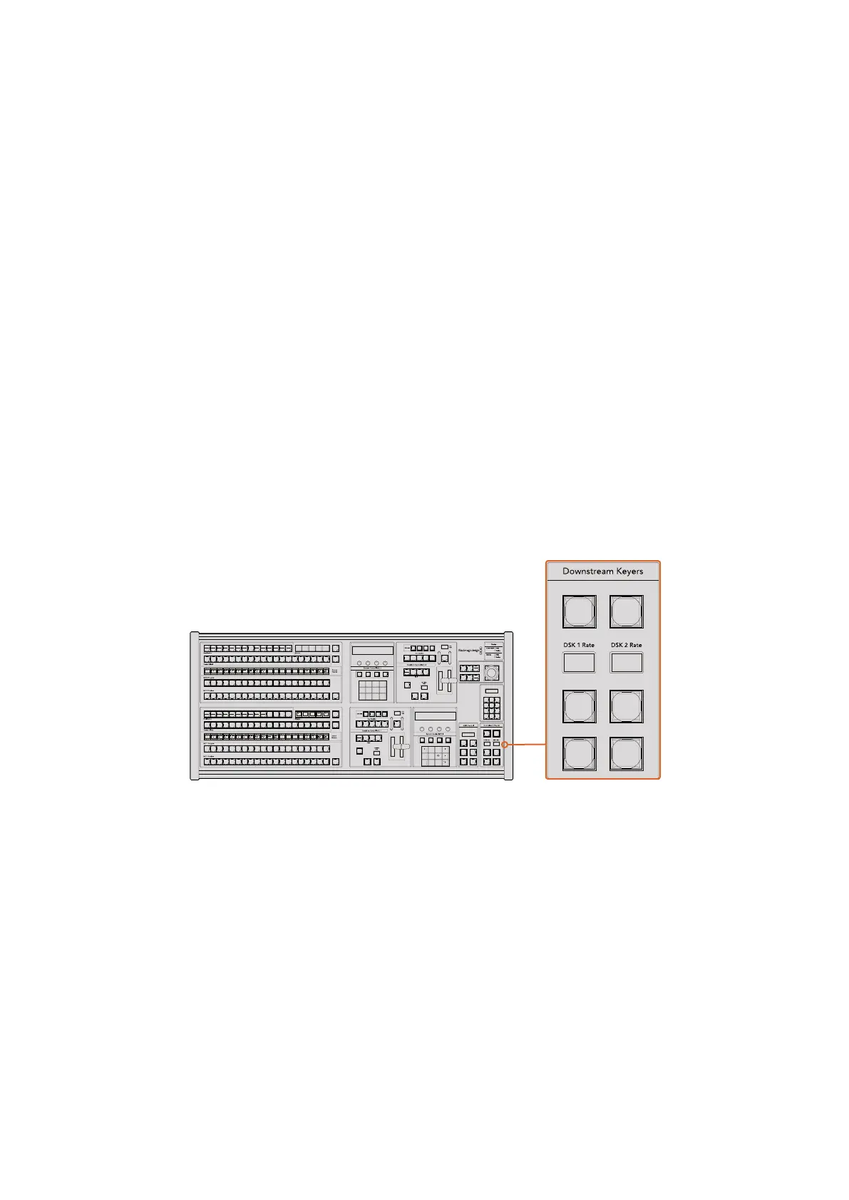
Downstream Keyers
DSK TIE
The DSK TIE button will enable the DSK on the preview output, along with the next transition
effects, and tie it to the main transition control so that the DSK can be taken to air with the next
transition.
Because the tied downstream keyer is now tied to the main transition, the transition will happen
at the rate specified in the transition rate display of the transition control block. When the DSK is
tied, the signal routing to the clean feed 1 is unaffected.
DSK CUT
The DSK CUT button is used to cut the DSK on or off air and indicates whether the
DSK is currently on or off air. The button is illuminated if the DSK is currently on air.
DSK AUTO
The DSK AUTO button will mix the DSK on or off air at the rate specified in the DSK
rate window.
Fade to Black
The FTB button will fade the program output to black at the rate specified in the FTB rate
window. Once the program output has been faded to black, the FTB button will flash red until it
is pressed again, fading the program output up from black at the same rate. A fade to black
cannot be previewed. You can also set your audio mixer to automatically fade the audio with
your fade to black by selecting the master fader’s AFV button.
Downstream Keyers and Fade to Black
System Status
The status lights provide feedback on the internal or external power supplies running the
broadcast panel and switchers. Not all ATEM switcher models have redundant power supplies
so sometimes you will only see a single light illuminated for the power status of the switcher.
However if your switcher model has redundant power and you have two power supplies
connected on the switcher and the control panel, then all the lights should be on. In this
situation where you are using redundant power supplies, any light that turns off could indicate
a power supply or cable is faulty, and this should be checked.
When the 2 M/E panel is used to control two ATEM switchers, the switcher status lights indicate
whether the two switchers are powered on. In this context, the “Main” switcher status light
refers to the lower M/E 1 control block, and “Backup” refers to the upper M/E 2 control block.
1
8 9
0 CLRCAM
2 3
4 5 6
7
ON ON ON ON
ON ON ON ON
SHIFT
SHIFT
SHIFT
SHIFT
KEY 1
CUT
KEY 2
CUT
STNG
CUT
DVE
CUT
AUX 1
AUX 7
AUX 2
AUX 8
AUX 3
AUX 9
AUX 4
AUX 10
AUX 5
AUX 11
AUX 6
AUX 12
BORD
DIP
KEY 3
CUT
KEY 4
CUT
SHIFT
DEST
KEY 1
CUT
BORD
DIP
STNG
CUT
DVE
CUT
DSK 2
CUT
SSRC
CUT
BOX 1
DSK 1
CUT
KEY 2
CUT
KEY 3
CUT
KEY 4
CUT
BOX 3BOX 2 BOX 4
SHIFT
DEST
TIE
DSK 1
TIE
DSK 2
CUT
DSK 1
CUT
DSK 2
AUTO
DSK 1
AUTO
DSK 2
WIPE STNG DVE
MIX
DIP
BKGD KEY 1 KEY 2 KEY 3 KEY 4
WIPE STNG DVE
MIX
DIP
BKGD KEY 1 KEY 2 KEY 3 KEY 4
BOX 2
BOX 4
PATT
M/E 2
KEY
M/E 2
BOX 2
BOX 4
PATT
M/E 1
KEY
M/E 1
AUTOCUT
FTB
FTB
PREV
TRANS
AUTOCUT
PREV
TRANS
TRANS
DSK
KEYS
EFFECTS
KEYS
MEDIA
PLAYER
PANEL
SETUP
COLOR
MACRO
1
RECALL
& RUN
PLAY
RECORDLOOP
PLAY
RECORD
SHOW
NAMES
RECALL
DELETE
HOME
STOP
LOOP
MACRO
1
RECALL
PLAY
RECORDLOOP
1
8 9
0 CLRCAM
2 3
4 5 6
7
ON ON ON ON
ON ON ON ON
SHIFT
SHIFT
SHIFT
SHIFT
KEY 1
CUT
KEY 2
CUT
STNG
CUT
DVE
CUT
AUX 1
AUX 7
AUX 2
AUX 8
AUX 3
AUX 9
AUX 4
AUX 10
AUX 5
AUX 11
AUX 6
AUX 12
BORD
DIP
KEY 3
CUT
KEY 4
CUT
SHIFT
DEST
KEY 1
CUT
BORD
DIP
STNG
CUT
DVE
CUT
DSK 2
CUT
SSRC
CUT
BOX 1
DSK 1
CUT
KEY 2
CUT
KEY 3
CUT
KEY 4
CUT
BOX 3BOX 2 BOX 4
SHIFT
DEST
TIE
DSK 1
TIE
DSK 2
CUT
DSK 1
CUT
DSK 2
AUTO
DSK 1
AUTO
DSK 2
WIPE STNG DVE
MIX
DIP
BKGD KEY 1 KEY 2 KEY 3 KEY 4
WIPE STNG DVE
MIX
DIP
BKGD KEY 1 KEY 2 KEY 3 KEY 4
BOX 2
BOX 4
PATT
M/E 2
KEY
M/E 2
BOX 2
BOX 4
PATT
M/E 1
KEY
M/E 1
AUTOCUT
FTB
FTB
PREV
TRANS
AUTOCUT
PREV
TRANS
TRANS
DSK
KEYS
EFFECTS
KEYS
MEDIA
PLAYER
PANEL
SETUP
COLOR
MACRO
1
RECALL
& RUN
PLAY
RECORDLOOP
PLAY
RECORD
SHOW
NAMES
RECALL
DELETE
HOME
STOP
LOOP
MACRO
1
RECALL
PLAY
RECORDLOOP
191