1 689 989 234 2018-06-08| Robert Bosch GmbH
18 | BAT 690 | Operationen
¶ Set the On/Off switch to "0" (OFF) before
connecting the BAT 690 to the mains voltage system.
¶ When charging vehicle batteries in the installed
condition, connect the black terminal clip (‒) to the
body, away from the battery and fuel pipe line.
¶ Switch off the BAT 690 before disconnecting the
charging clips.
¶ Never disconnect the terminal clips while a battery
is being charged.
¶ Never disconnect the battery from the vehicle
electrical system whilst charging is in progress.
¶ Never short-circuit charging clips.
i In the event of incorrect polarity and terminal short-
circuit no charging voltage is applied and an failure
indication appears.
5.2 Switching on
1. Connect the BAT 690 to the mains voltage system via
the power supply cable.
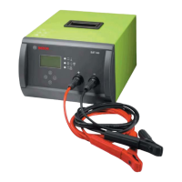
2. Switch on the BAT 690 via the on/off switch (fig.1,
item1).
The red LED (fig.1, item7) lights up if the bat-
tery is connected or flashes if it is not connected.
i After switching the device on or after resetting it to
factory settings, the "Language settings" menu is
displayed automatically.
i After the BAT 690 is switched on, the voltage is
displayed when the battery is connected or if the
battery is not connected, the message "no battery
connected" appears.
i The BAT 690 automatically detects whether a 12V
or a 24V battery (series connection of two 12V
batteries) is connected.
Minimum voltage by mode 12V 24V
No mode (e.g. after switching the device on) 3V 17V
Charging 3V 17V
Charging (LFP) 9V 18V
Support 3V 17V
Buffering 9V 18V
Tab. 1: Battery detection
5.3 Charging mode
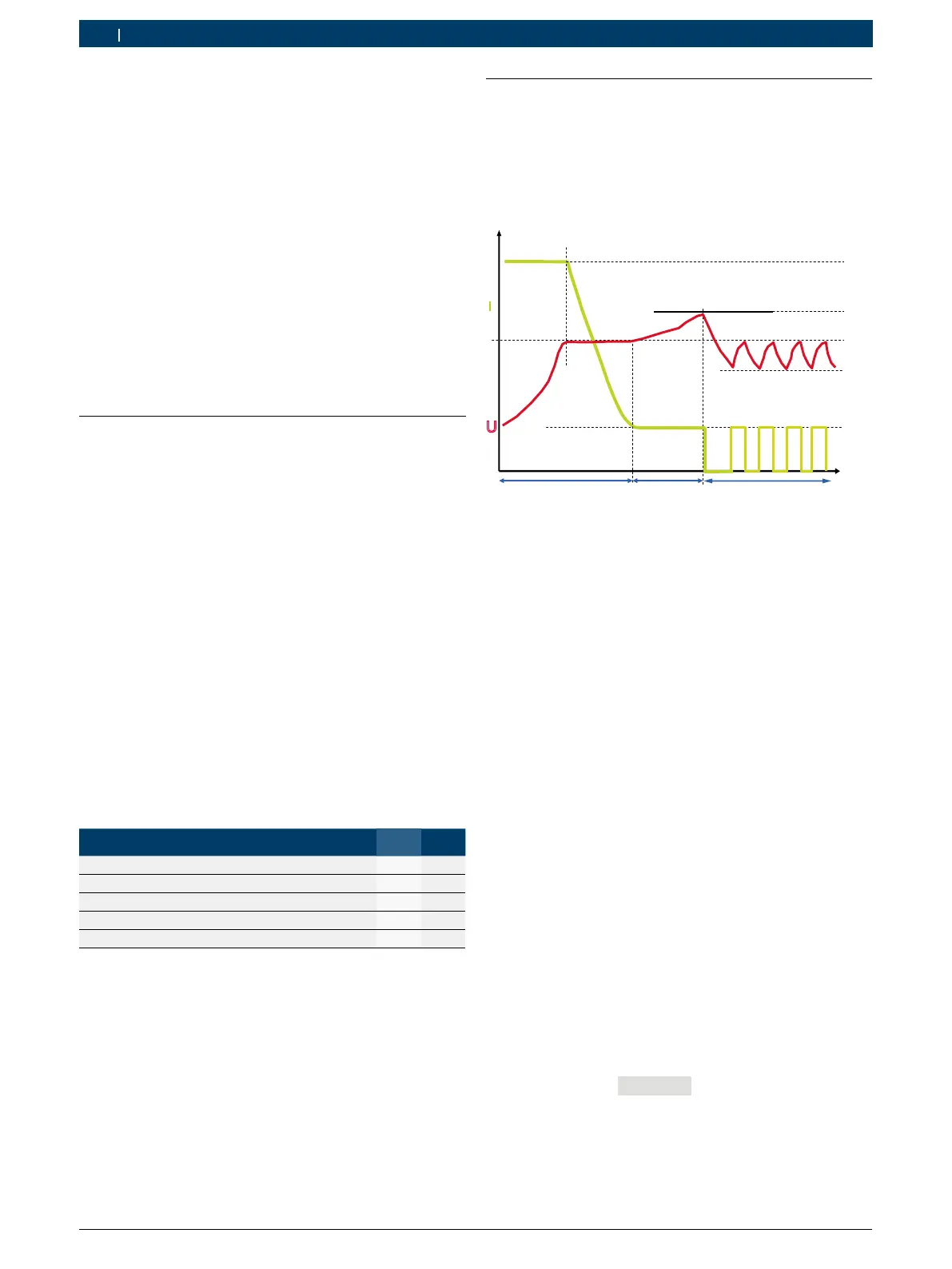
Charging characteristics
Various charging characteristics and charging
parameters are stored in the BAT 690, depending on
the battery type. The figure below is an example which
shows the principle of a battery charging characteristic.
t
I
U
I
1
I
2
U
U
Fig. 4: Charging characteristic
Characteristic values for UNI battery type
I
1
= 20% of set battery capacity
I
2
= 2 of set battery capacity
U
1
=
14.0V (12V), 28.0V (24V)
U
2
= 14.2V – 14.8V (12V), 28.4V – 29.6V (24V)
U
3
=
13.5V / 27V
Phase 1 (t1): Main charging, green LED flashes rapidly
The charging current I
1
is approx. 20% of the set
battery capacity (60% with LFP batteries). Once the
battery has attained the charging cut-off voltage U
1
, the
charging current I
1
starts to decrease. Approx. 65% of
the battery capacity has then been attained. The battery
is ready for use as a starter battery. Phase1 is over
when the charging current I
1
drops below approx. 2%
of the battery capacity. The battery is then approx. 97%
charged.
Phase 2 (t2): Secondary charging, green LED flashes
slowly
The charging current I
2
is approx. 2% of the set battery
capacity. The charge voltage is limited to U
2
.
Phase 3 (t3): Trickle charging, green LED lights up
The charging current is always activated when the
battery voltage drops below U
3
. The charging current
remains active until the charging voltage U
1
is attained
again.
i If the message "Time out" is displayed, a charging
phase could not be completed. This indicates that
either the parameter was entered incorrectly, or that
the battery is defective.
 Loading...