53-1002177-19 Hardware Installation Guide
Brocade DCX 8510-4 Backbone Hardware Installation Guide
The following table describes the connector port LED patterns and the recommended actions for those patterns.
Table 9: ICL QSFP connector port LEDs
LED purpose Color Status Recommended action
No light (LED is off) No QSFP module, all four QSFP
ports are disabled.
No action is required if QSFP
not present or verify that the
QSFP is fully inserted.
Steady amber QSFP module is in, all four ports
have no signal/no sync.
No action required if QSFP only
is installed or ensure that the
cable is properly connected. If
the LED remains amber, consult
the device supplier.
Blinking amber Port is disabled or faulted,
FC link activity, segmented,
loopback mode, also during
transition between MTP cable
insertion and confirmation.
Check for console messages
or wait for all four ports to come
online.
QSFP connector status
Steady green Both ends of MTP cable are in
and all ports are online. Full link
is established.
No action required.
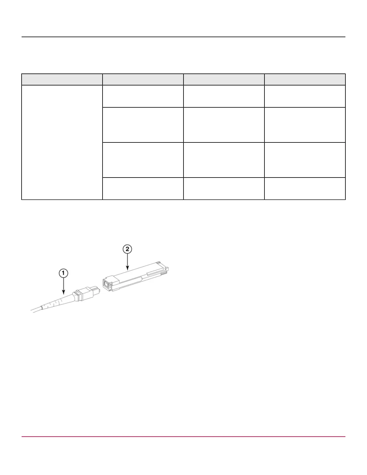
The following figures illustrate types of MTP cables and transceivers:
•
Separate MTP cable and transceiver. The transceiver is inserted into the blade port connector and the cable plugs into
a QSFP on the other end of the ICL.
Figure 31: MTP cable and transceiver
1. MTP cable
2. Transceiver
NOTE
If the fiber optic cables are not connected to transceivers, make sure the rubber gaskets are plugged into the
transceivers.
•
Brocade 2 km LWL QSFP transceiver with integrated MTP cable. The transceiver is inserted into the blade port
connector and integrated cable plugs into a QSFP on the other end of the ICL, a patch panel, or a patch cable.
53-1002177-19
58