53-1002177-19 Hardware Installation Guide
Brocade DCX 8510-4 Backbone Hardware Installation Guide
Complete the following steps to replace the core switch blade.
1. Open the ejectors by rotating them toward the center of the blade face. Orient the CR blade so that the handles are
toward you.
2. Align the flat side of the blade inside the left and right rail guides in the slot with the components facing upwards, and
slide the blade into the slot until it is firmly seated.
3. Close the ejectors by rotating them away from the center of the blade. The levering action of the ejectors seats the
blade in the slot.
4. Power on the blade by screwing in the thumbscrews.
5. Verify that the power LED is green (might require a few seconds). If not, ensure that the core switch blade has power
and is firmly seated and that the ejectors are in the locked position.
6. Verify that the status LED on the new blade is initially amber and will be until POST for the blade completes. this may
take as long as several minutes. It then turns green.
7. Connect the cables to the new core switch blade. For the DCX 8510 models, if the QSFP cables are not used, make
sure the rubber gaskets are in the QSFP transceivers.
8. Replace the chassis door.
9. Pack the faulty core switch blade in the packaging provided with the new core switch blade, and contact the device
supplier to determine the return procedure.
Power supply removal and replacement
Use this procedure to remove and replace a power supply.
NOTE
Depending on the blade configuration of the chassis and the number of power supplies installed, the device
may be able to continue operating during the replacement. Refer to the power supply specifications section
in the Brocade DCX 8510 Backbone Technical Specification for this DCX device to determine your power
requirements. If there is insufficient power, the chassis will start powering down blades until the power demand
can be met. The device power supplies are 100-240 VAC, autosensing.
NOTE
A chassis with slots for eight port blades can have up to four power supplies installed. If you are adding
additional power supplies, you can use the procedures in this section under "Replacing a power supply" to
install the new power supplies. Be sure to follow steps on those procedures to enable sending notifications if the
additional power supplies should fail.
Time and items required
The replacement procedure for each power supply takes less than five minutes. A power supply unit or filler panel is
required for the power supply replacement.
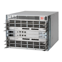
Identifying power supplies
The following figure shows the location and identification of the power supplies.
53-1002177-19
122