Electrical and Ignition
Charging System Tests
104
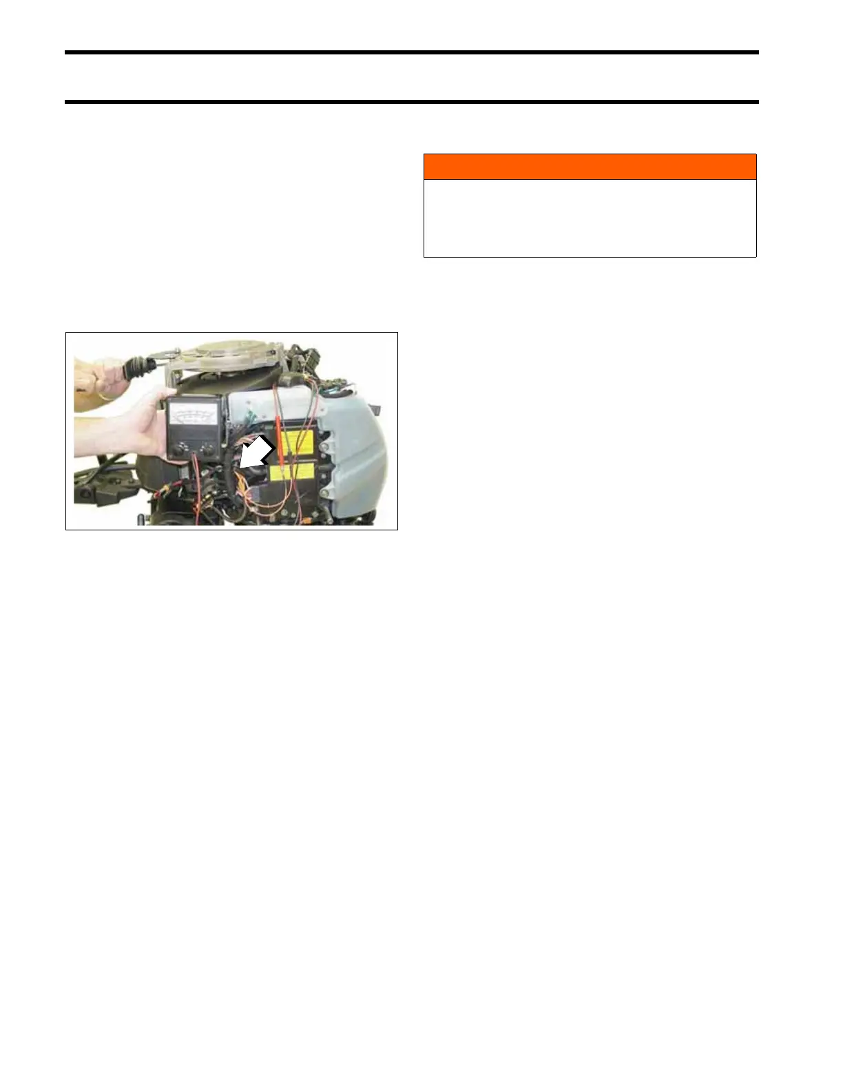
Disconnect stator (6-pin) connector from the
engine harness (6-pin) connector.
Connect Stator Test Adaptor tool, P/N 5005799, to
stator connector.
Connect meter leads to terminals of adaptor tool.
Rotate the flywheel with the starter rope, using a
long, steady pull.
Stator output voltage should be approximately
30 VAC.
IMPORTANT: Index all spark plugs. Refer to
Spark Plug Indexing on p. 43.
Charging System Tests
12 V Charging Circuit
To test the operation of the regulator in the EMM,
you must be able to run the outboard continuously
at approximately 5000 RPM, such as in a test tank
or on a marine dynamometer.
The test consists of monitoring the system’s
response to a partially discharged battery. Use a
variable load tester to discharge the battery.
IMPORTANT: The regulator requires voltage to
operate. Before proceeding, make sure there is at
least 7 V on the positive terminal of the starter so-
lenoid.
Disconnect the battery cables at the battery.
Use an inductive amp meter or connect a 0 to
50 A ammeter in series between the red wire of
engine wire harness (alternator output from EMM)
and the positive (B+) battery cable terminal of
starter solenoid.
Fluke
†
model 300 series, or Snap-On
†
model
EETA500 series, and various other amp meters
should be available through local tool suppliers.
Reconnect the battery cables.
Following the manufacturer’s directions, connect
the variable load tester (carbon pile) across the
battery terminals. Stevens model LB-85 and
1. Stator Test Adaptor
006750
WARNING
Excessive battery discharge rates might
overheat battery causing electrolyte gas-
sing. This might create an explosive atmo-
sphere. Always work in a well ventilated area.