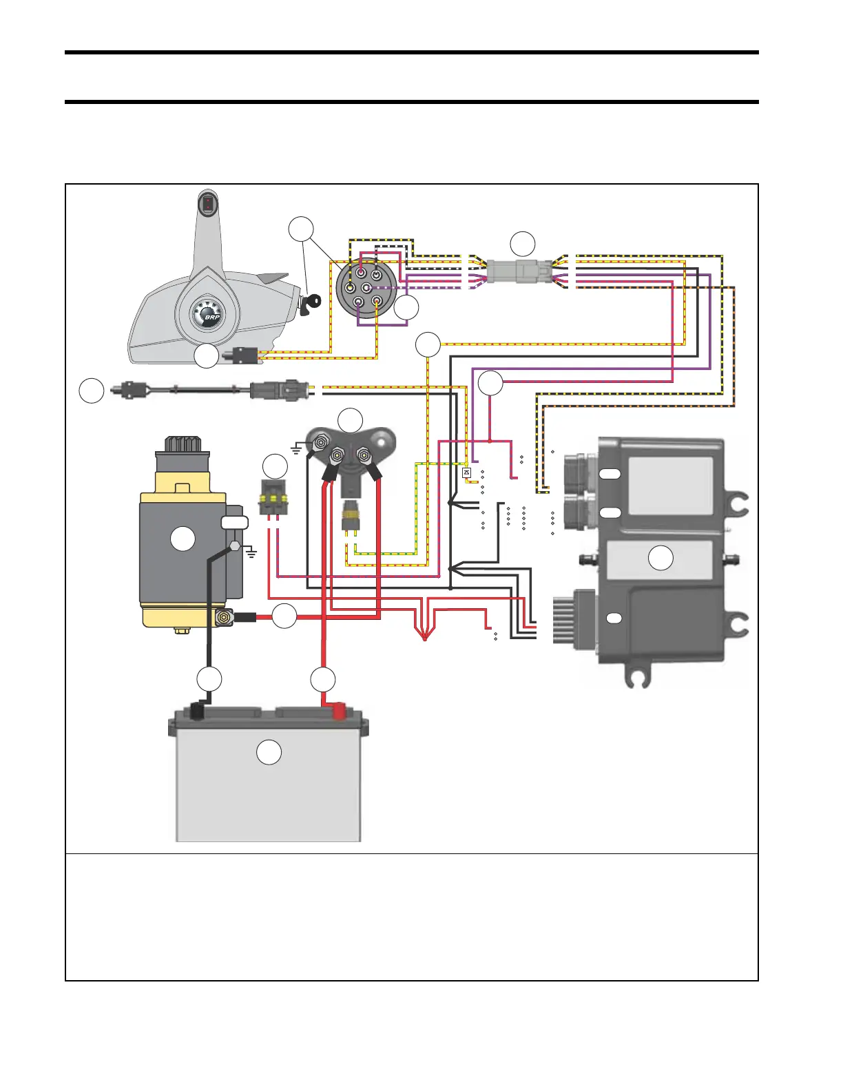
EasyManua.ls Logo

BRP E-TEC EVINRUDE - Electric Start Circuit

BRP E-TEC EVINRUDE
364 pages
Print Icon
To Next Page IconTo Next Page
To Previous Page IconTo Previous Page
Loading...
106
Electrical and Ignition
Electric Start Circuit
Start Circuit Diagram
NEG
1
2
3
4
5
6
7
8
9
10
11
12
13
14
15
16
17
18
19
20
21
22
23
24
25
26
27
28
29
30
31
32
33
34
1
2
3
4
5
6
7
8
9
10
11
12
13
20
21
22
23
24
25
26
14
15
16
17
18
19
1
2
3
4
5
6
7
8
9
10
11
12
13
14
15
16
010349
M
A
S
C
M
B
1
2
3
4
5
6
– +
5
J1-A
J1-B
J2
A B
A B
1
2
1
2
3
4
5
6
6
12
13
3
4
10
11
1
2
9
15
7
14
8
1. Marine battery
2. RED wire (POS)
3. BLACK wire (NEG)
4. Starter solenoid
5. Fuse (10 amp)
6. RED/PURPLE wire
7. Key switch connectors
8. Ignition switch
9. PURPLE wire (switched B+)
10. Engine Management Module (EMM)
11. YELLOW/RED wire, start
12. Neutral Safety Switch (remote control)
13. Neutral Safety Switch (engine)
14. RED starter motor cable
15. Electric starter motor

Table of Contents

Related product manuals