Fuel System
Fuel Component Servicing
156
Install washers (one per screw) on injector retain-
ing screws. Install screws and washers through
mounting flange of injector and into cylinder head.
Tighten screws in stages, starting with the lower
screw.
• First torque is 5 ft. lbs. (7 N·m).
• Second torque is 10 ft. lbs. (14 N·m).
• Final torque is 24 to 26 ft. lbs. (33 to 35 N·m).
Reconnect fuel injector electrical connectors.
Install the ignition coil assemblies. Tighten coil
screws to a torque of 60 to 84 in. lbs (7 to 9.5
N·m).
Install fuel manifolds. Refer to Fuel Manifold Ser-
vice on p. 151.
Intake Manifold Service
Removal
Disconnect vapor separator vent hose, main bear-
ing vent hose, air temperature sensor, crankshaft
position sensor, and throttle position sensor.
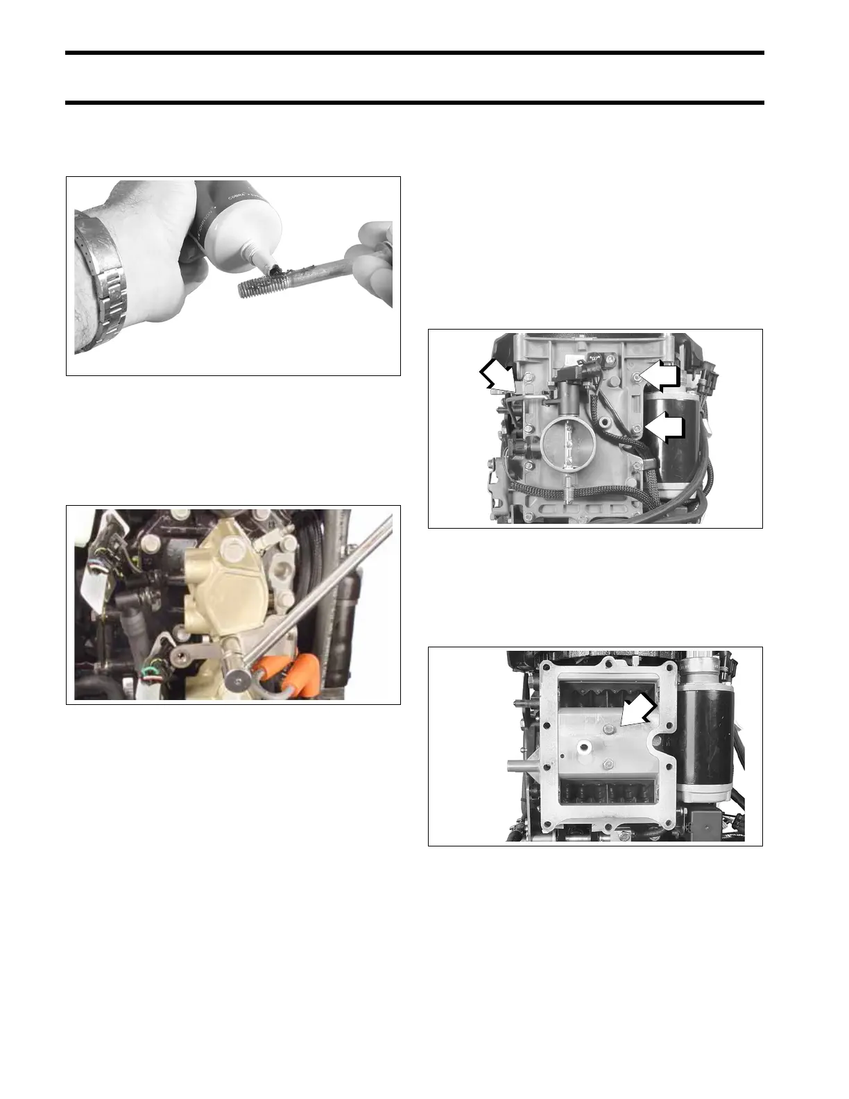
Use Ball Socket Remover Tool, P/N 342226, to
remove throttle link arm.
Remove throttle body screws and throttle body
assembly.
Remove gasket from throttle body.
Remove screws and reed plate assembly from the
crankcase.
Disassembly
All reed plate assembly and reed valve assem-
blies must be cleaned prior to reassembly. DO
NOT use strong carburetor cleaner or the hot
soaking tank method for cleaning.
002316
Tighten Screws in Stages
006562
1. Link arm
2. Throttle body screws
002499
1. Screws
002503