277
Midsection
Tiller Handle Service – Standard
11
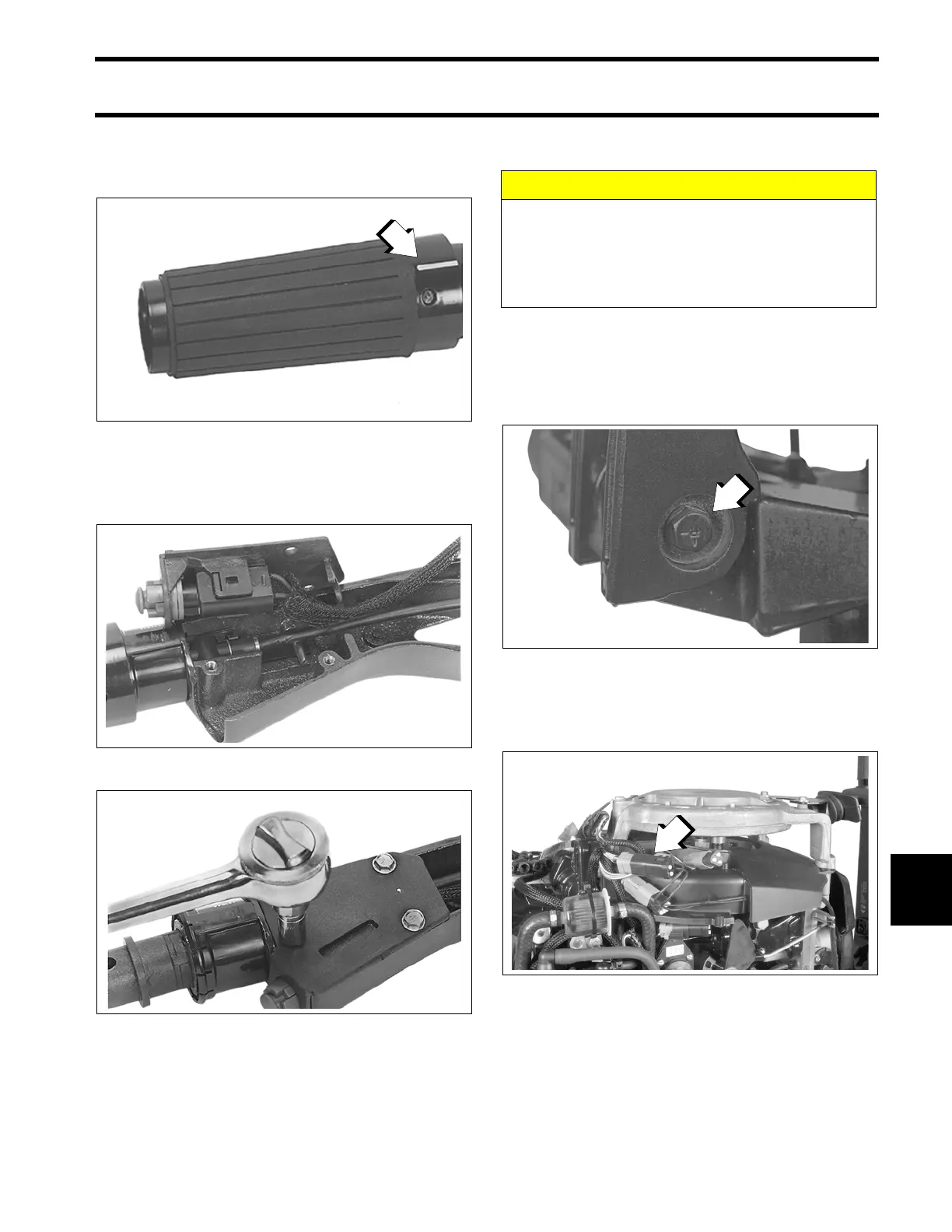
Be sure the twist-grip's speed indicator line is
positioned with the speed range symbol on the
handle. Snap the grip into place.
Slide the protective sleeve over the stop switch
leads and throttle cable and install stop switch
cover.
Installation
Apply Triple-Guard grease to the two steering
handle bushings. Place the bushings into the
steering bracket. Attach the steering handle to the
bracket. Tighten screw to a torque of 36 to 40 ft.
lbs. (49 to 54 N·m).
Route throttle cable and electrical harness
through grommet in lower motor cover. Connect
harness to engine wiring harness.
1. Indicator line
002190
24291
24288
CAUTION
The steering handle nut must have a nylon
patch for locking. Replace the nut if it has
lost its locking feature. Tighten the nut so the
steering handle can be pivoted and main-
tained in any position.
1. Screw
31194
1. Electrical harness connector
002511