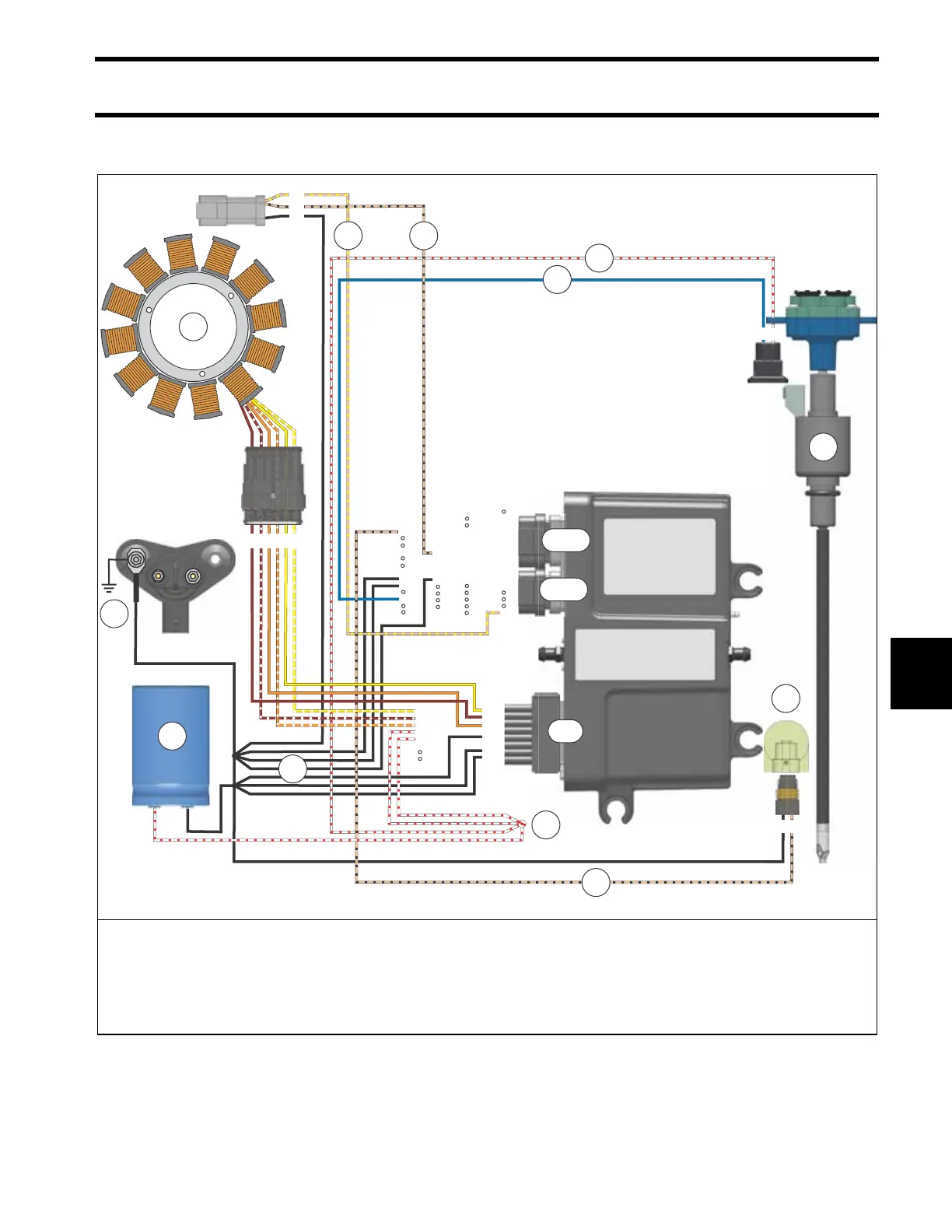
EasyManua.ls Logo

BRP E-TEC EVINRUDE - Oiling System Circuit Diagram

BRP E-TEC EVINRUDE
364 pages
Print Icon
To Next Page IconTo Next Page
To Previous Page IconTo Previous Page
Loading...
Oiling System
Oiling System Circuit Diagram
165
8
Oiling System Circuit Diagram
1
2
3
4
5
6
7
8
9
10
11
12
13
14
15
16
17
18
19
20
21
22
23
24
25
26
27
28
29
30
31
32
33
34
1
2
3
4
5
6
7
8
9
10
11
12
13
20
21
22
23
24
25
26
14
15
16
17
18
19
1
2
3
4
5
6
7
8
9
10
11
12
13
14
15
16
1
2
4
7
8
3
J1-A
J1-B
J2
010347
B A
6 5 4 3 2 1
6
5
4
3
2
1
5
6
9
10
11
12
B A
1. Stator
2. Main harness ground (BLACK)
3. Alternator grounds (BLACK)
4. Alternator output, WHITE / RED wires (55 V)
5. Capacitor (55 V)
6. EMM injector control (BLUE)
7. 55 V to injection pump (WHITE / RED)
8. Oil injection pump
9. Low oil switch
10. Low oil switch to EMM (TAN/BLACK)
11. Low oil signal to SystemCheck gauge (TAN/BLACK)
12. No oil signal to SystemCheck gauge (TAN/YELLOW)

Table of Contents

Related product manuals