System Analysis
Ignition Output Tests
88
Steady spark on all cylinders:
• Refer to Running Ignition Tests on p. 88 and
Dynamic Tests on p. 83.
Running Ignition Tests
Use Evinrude Diagnostics Software to monitor
system voltage (55 V).
• Voltage readings at a specific speed (RPM)
should be steady
• Refer to System Voltage Test on p. 86.
Use an inductive timing light to monitor the spark
signal through each of the secondary circuit
(spark plug lead) wires.
Start outboard and observe timing light strobe.
Look for a consistent flash and only one flash per
revolution. The strobe of the timing light should be
the same for each cylinder.
Results:
Steady voltage and strobe, engine misfires:
• Inspect or replace spark plugs
• Refer to Fuel Delivery Tests on p. 90
• Check for internal engine damage.
Steady voltage, erratic strobe, engine misfires:
• Inspect or replace spark plugs
• Check CPS air gap and resistance.
• Refer to Ignition Control Circuit Tests on
p. 88
• Refer to Ignition Coil Tests on p. 89.
Voltages fluctuate, engine misfires:
• Inspect battery and connections
• Test capacitor and all ground connections.
• Refer to System Voltage Test on p. 86
• Refer to Ignition Control Circuit Tests on
p. 88
• Refer to Ignition Coil Tests on p. 89.
IMPORTANT: If a running problem occurs at
about 1200 RPM, the outboard may be in S.A.F.E.
Refer to S.A.F.E. Warning System on p. 68.
Ignition Control Circuit Tests
Use a digital multimeter to test the following:
• System voltage supply to ignition coil.
• Ignition control signal from EMM.
• Engine harness resistance.
Disconnect ignition coil connector.
Supply voltage test:
Use an appropriate adapter to connect the red
meter lead to pin 3 (white/red) of the engine har-
ness connector and the black lead to ground. With
EMM ON, voltage should be approximately 1 V
less than battery voltage.
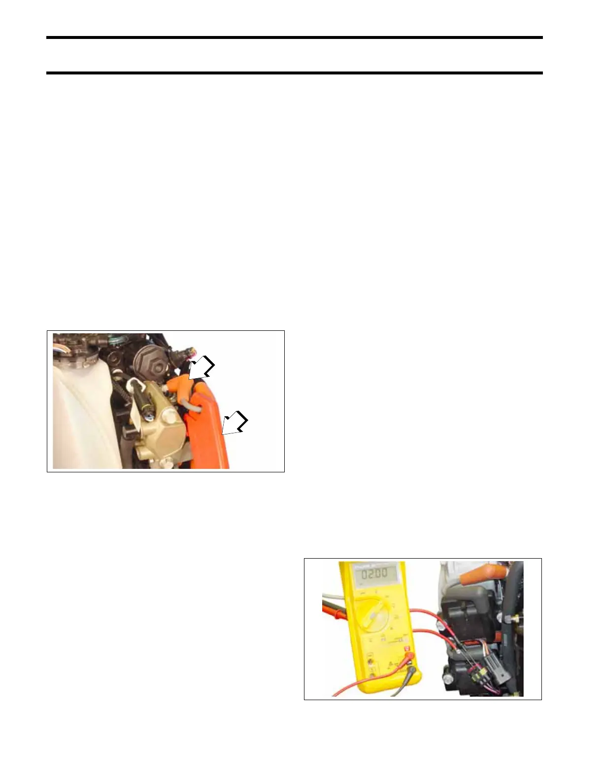
Control signal test:
Set meter to the Hz scale to check ignition control
signal.
Use an appropriate adapter to connect the red
meter lead to pin 2 (orange) of the engine harness
connector and the black lead to ground. Activate
diagnostics software Static Ignition test and
observe meter for consistent reading (approxi-
mately 2 Hz).
If control signal is present, connect black meter
lead to pin 1 (black) and repeat test to confirm
harness ground.
1. Timing light pick-up
2. Spark plug lead
006492
006609