119
Electrical and Ignition
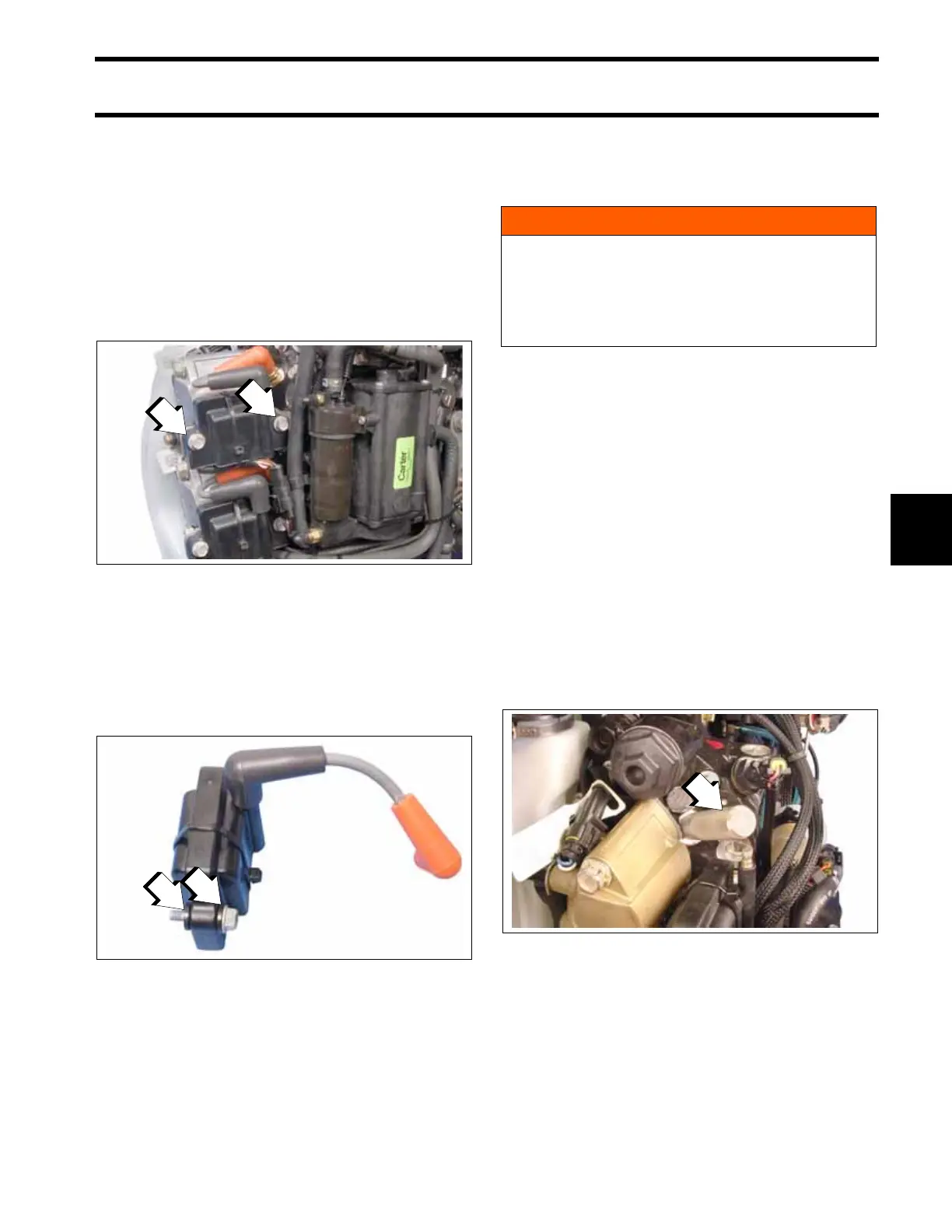
Ignition Coil Servicing
6
Ignition Coil Servicing
Ignition Coil Removal
Remove spark plug lead from ignition coil and dis-
connect ignition coil electrical connector.
Remove two ignition coil retaining screws.
Do not lose the rubber washers between coil and
bracket.
Ignition Coil Installation
Install one rubber washer on each screw and
install screw through ignition coil.
Install remaining rubber washers on screws
between coil and bracket.
Install coil on bracket. Tighten screws to a torque
of 60 to 84 in. lb. (7 to 9.5 N·m).
Install spark plug lead on ignition coil and connect
ignition coil electrical connector.
Timing Adjustments
Timing Pointer
The timing pointer must be adjusted to indicate
top dead center (TDC) of the number 1 piston.
This reference to the position of the number 1 pis-
ton is used to synchronize the electronic timing
controlled by the EMM with the mechanical posi-
tion of the number 1 piston.
Always check timing pointer adjustment before
using the Evinrude Diagnostics software Timing
Verification procedure.
Disconnect the battery cables at battery.
Remove spark plugs. Rotate the flywheel clock-
wise to approximately 30° ATDC.
Install Piston Stop Tool, P/N 342679, into the
spark plug hole of the number 1 cylinder.
Rotate flywheel counterclockwise until the num-
ber 1 piston contacts the tool. Keep pressure on
the flywheel to position the piston firmly against
1. Screws
008187
1. Rubber washers
008188
WARNING
To prevent accidental starting of outboard:
• Disconnect the battery cables at the bat-
tery.
• Disconnect crankshaft position sensor
(CPS).
1. Piston stop tool
006493