System Analysis
Ignition Output Tests
86
• Outboard cranking speed exceeds 300 RPM
and a steady CPS signal is generated.
Alternator Output/System Voltage
•
System voltage from EMM (white/red) provides
55 VDC to the high pressure fuel pump, the oil
injection pump, the fuel injectors, and the igni-
tion coils.
Capacitor
•
Connected to 55 V circuit (white/red) to stabilize
current on 55 V circuit
• Negative terminal of capacitor must be
grounded.
Ignition Coil
• Primary circuits are powered by system (55 V)
voltage
• EMM provides control signal to ignition coil
• Output from ignition coil secondary winding and
high tension spark plug wire.
Wiring Inspection
Visually inspect all wiring, connections, and
grounds.
Use a digital ohmmeter to test resistance on all
ground circuits and connections. Ohmmeter read-
ings should be approximately 0.0 W.
Check that all engine wire harness grounds have
continuity to the cylinder/crankcase.
Clean or repair all ground circuits, wiring, and con-
nections as needed.
Crankshaft Position Sensor (CPS)
Test
When the CPS is working properly, EMM LED 2
turns on while the outboard is being started.
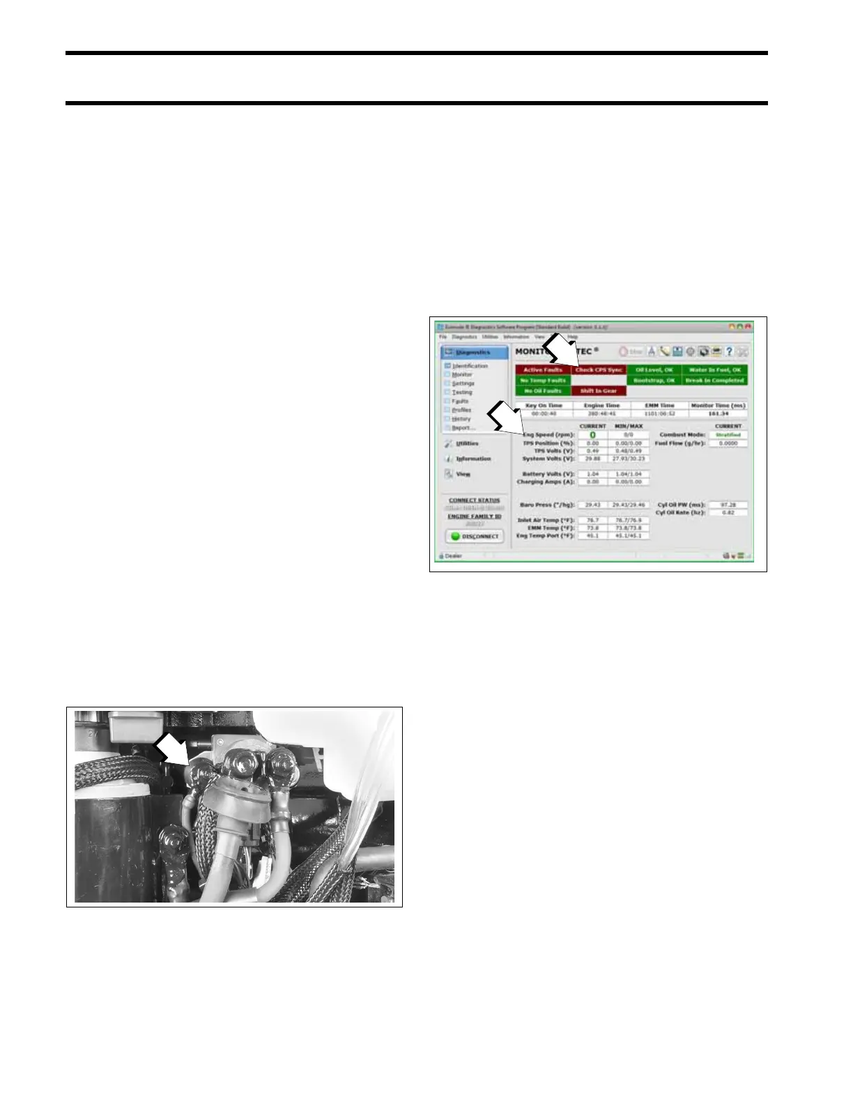
Use the Evinrude Diagnostics software CPS Sync
and engine RPM displays to confirm a valid CPS
signal while the outboard is cranking or running.
An RPM display higher than zero indicates a CPS
signal to the EMM.
If the Monitor screen says “Check CPS Sync,”
refer to Crankshaft Position Sensor (CPS) Test
on p. 101.
System Voltage Test
The ignition system is powered by the 55 V sys-
tem.
1. Main engine harness ground
002292
Engine RPM and CPS Sync displays
008566A