49
Routine Service
Gearcase Removal and Installation
2
Slide the gearcase into place, making sure:
• Driveshaft engages the crankshaft.
• Water tube enters the water pump.
• Lower inner exhaust housing installs correctly.
• Shift rod does not turn and is positioned prop-
erly in the shift rod lever below the crankcase.
IMPORTANT: New gearcase screws are treated
with a thread-locking material. Apply Triple-Guard
grease to threads to ensure that the correct clamp-
ing force is achieved when tightening—If a previ-
ously installed screw is re-used, use a wire brush
to remove any old thread-locking material or corro-
sion and lubricate threads with Triple-Guard
grease.
Install screws and washers and tighten to a torque
of:
• 3/8 in. screws – 26 to 28 ft. lbs. (35 to 38 N·m)
• 7/16 in. screws – 45 to 50 ft. lbs. (61 to 68 N·m)
Place the shift rod in the shift rod lever. Install the
retaining pin and washer. Tighten pin to a torque
of 60 to 84 in. lbs. (7 to 9.5 N·m).
1. 3/8 in. screws
001990
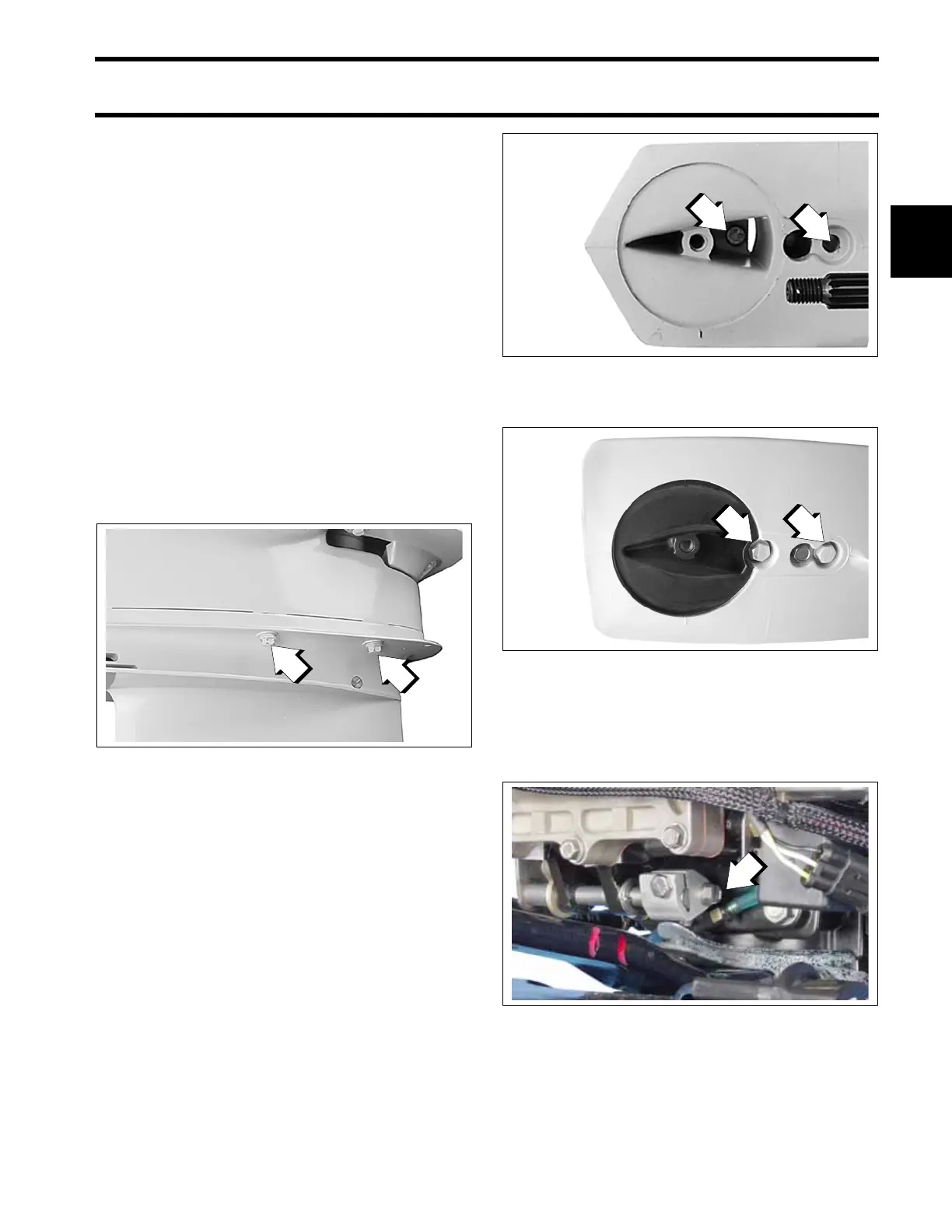
S Type Gearcases
1. 3/8-16 x 1.75 in. screw
2. 7/16-14 x 3.5 in. screw
COA3139
O Type Gearcases
1. 3/8-16 x 3.5 in. screw
2. 7/16-14 x 3.5 in. screw
006869
2-Cylinder Models
1. Shift rod screw
002171