3-30 2002 Buell P3: Engine
HOME
Grinding Valve Faces and Seats
After installing valve guides, reface valve seats to make them
concentric with guides.
See Figure 3-57. Valve face angle is 45° for both intake and
exhaust valves. If a valve re-facing grinder is used, it must be
adjusted exactly to this angle.
NOTES
● It is important to remove no more metal than is neces-
sary to clean up and true valve face.
● Install a new valve if grinding leaves the valve edge
(the margin) with a width of less than 1/32 in. (0.8
mm).
CAUTION
Do not use valves with too thin of margins. Using a valve
with too thin a margin does not seat normally, burns eas-
ily, may cause pre-ignition and can also lead to valve
cracking.
● Valves that do not clean up quickly are probably
warped or too deeply pitted to be reused.
● Replace the valve if end of valve stem shows uneven
wear.
● After valves have been ground, handle with care to
prevent damage to the ground faces.
The valve seats may be refinished with cutters or grinders.
Cut seats to a 46° angle or grind seats to a 45° angle.
See Tabl e 3-6. Valve seat tools and fixtures are available
commercially. Seat each valve in the same position from
which it was removed.
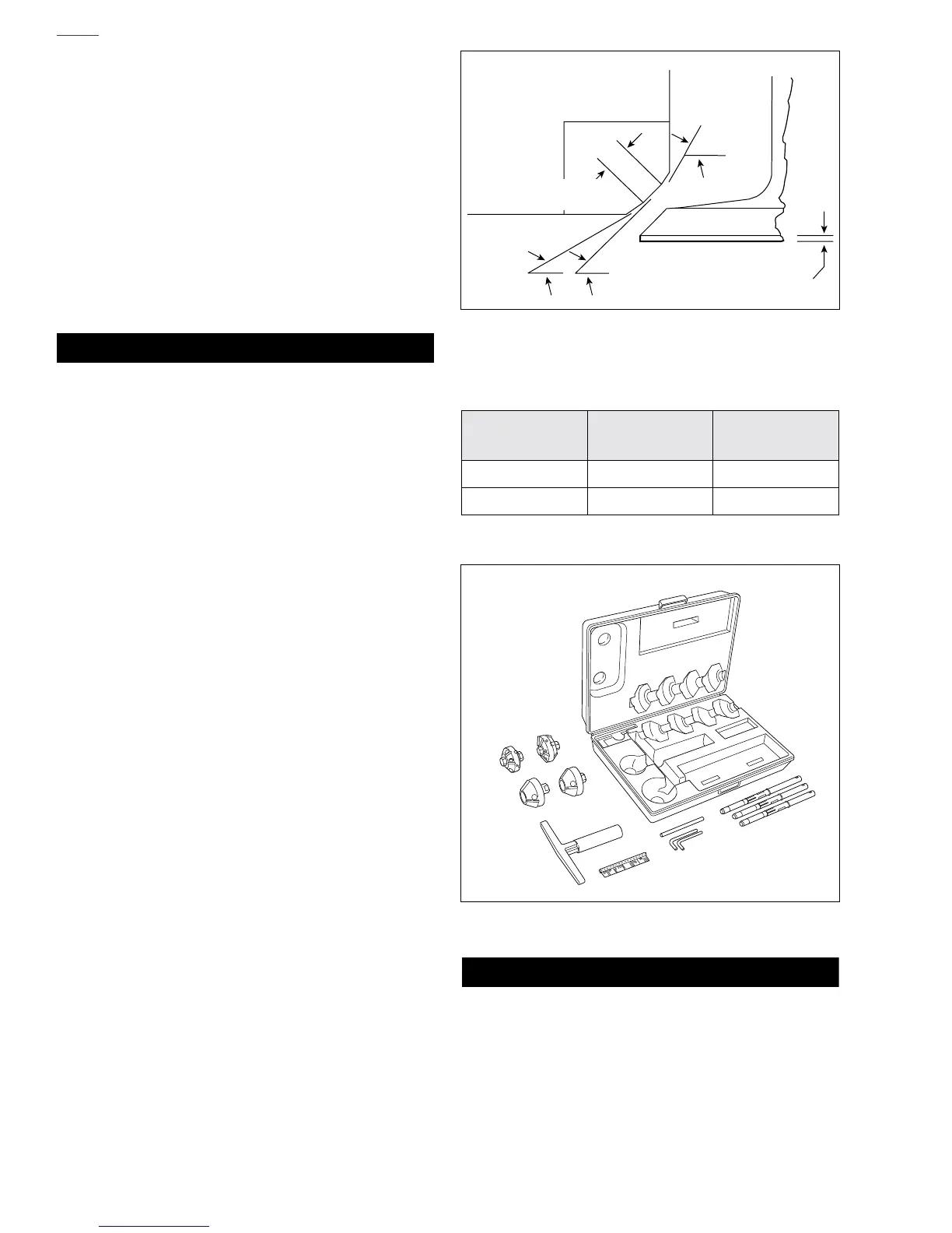
The correct 3-angle valve seat angles are as shown. Use
NEWAY VALVE SEAT CUTTER SET (Part No. HD-35758) to
cut the seats. Always grind valves before cutting seats.
1. See Figure 3-58. Cut 46° (or grind 45°) valve seat angle
first. Use cutting oil to avoid chatter marks. Cut or grind
only enough to clean up the seat.
2. Apply a small amount of lapping compound to the valve
face. Rotate valve against seat using VALVE LAPPING
TOOL (Part No. HD-96550-36A).
3. See Figure 3-57. Check the contact pattern on valve
face. It should be 0.040-0.062 in. (1.016-1.575 mm)
wide, and its center should be positioned 2/3 of the way
toward the outside edge of face.
4. If valve seat pattern is too close to the stem side of valve
face, cut a 60° angle in order to raise seat. If pattern is
too close to the edge of valve face, cut a 31° angle in
order to lower seat.
5. After cutting either or both 31° or 60° angles to position
seat, final cut 46° (or grind 45°) seat angle to obtain
proper 0.040-0.062 in. (1.016-1.575 mm) width.
6. Recheck valve seat width and location with lapping com-
pound as described in Step 2.
7. To achieve a smooth even finish, place a piece of 280 grit
emery paper under the cutter head and rotate cutter.
CAUTION
Do not grind valve to shorten. Grinding will remove the
case hardening and expose the stem’s mild steel core
resulting in rapid end wear.
8. See Figure 3-59. Wipe valve seats and valve faces
clean. Measure valve stem protrusion.
a. If valve stem protrudes more than 2.031 in.
(51.587 mm), replace valve seat or cylinder head.
b. If valve stem protrusion is acceptable, valves and
seats are ready for lapping.
Figure 3-57. Valve Seat Angles
Table 3-6. Neway Valve Seat Cutters
VALVE SEAT 60° CUTTER
31° AND 46°
CUTTERS
Exhaust Part No. 205 Part No. 622
Intake Part No. 293 Part No. 642
Figure 3-58. Valve Seat Cutter
Head
Valve
46° Cutting
45° Grinding
Seat
31°
0.040-0.062 in.
(1.016-1.575 mm)
60°
Margin
a0085x3x
a0087x3x