2002 Buell P3: Engine 3-33
HOME
INSTALLATION
If only cylinder head work was needed, reinstall cylinder head
following these instructions. If further repair is required, see
3.6 CYLINDER AND PISTON.
1. Coat mating surfaces of cylinder studs and head screws
with parts cleaning solution.
2. Scrape old oil and any carbon deposits from threads by
using a back-and-forth motion, threading each head
screw onto its mating cylinder stud.
3. Remove head screws from studs. Wipe or blow dry
thread surfaces.
4. Apply oil to stud threads and to the underside of the
head screw shoulder.
CAUTION
Only oil film must remain on the head screw surfaces.
Too much oil will pool in the head screw sleeve. Pooled
oil may prevent proper torque application and full thread
engagement.
5. Blow or wipe off excess oil from head screws.
6. Thoroughly clean and dry the gasket surfaces of cylinder
and cylinder head.
7. Install a new O-ring on each dowel.
CAUTION
O-rings help to properly position the head gasket. O-
rings must be installed before the head gasket.
8. Install a new head gasket to cylinder.
9. Carefully lower cylinder head over studs and position on
dowels. Use great care so as not to disturb head gasket.
CAUTION
The procedure for tightening the head screws is critical
to proper distribution of pressure over gasket area. It
prevents gasket leaks, stud failure, and head and cylin-
der distortion.
10. See Figure 3-45. For each cylinder head, start with
screw numbered one, as shown. In increasing numerical
sequence (i.e. – 1, 2, 3 and 4):
a. Tighten bolts to 8-10 ft-lbs (11-14 Nm).
b. Tighten bolts to 13-15 ft-lbs (18-20 Nm).
c. Loosen all screws.
11. After screws are loosened from initial torque, tighten
head screws in three stages. Tighten fasteners in
increasing numerical sequence (i.e. – 1, 2, 3 and 4).
a. Tighten each screw to 8-10 ft-lbs (11-14 Nm).
b. Tighten each screw to 13-15 ft-lbs (18-20 Nm).
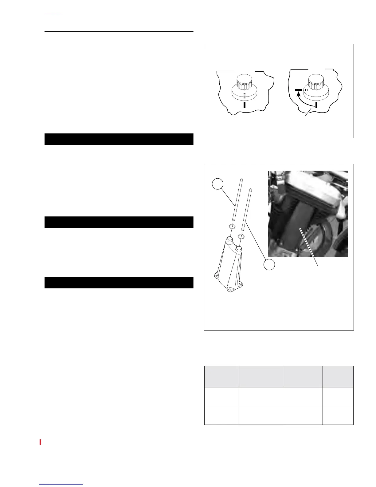
c. See Figure 3-63. Mark cylinder head and head
screw shoulder with a line as shown (View A).
d. Turn all bolts an additional 85 -95 .
12. See 3.15 HYDRAULIC LIFTERS. Install hydraulic lifters
and push rod cover.
13. See Figure 3-64. See Ta ble 3-7.Identify push rod color
coding, length and respective push rod positions in
engine. Place intake and exhaust push rods onto seat at
top of tappet.
°°
Figure 3-63. Tightening Head Screws
Figure 3-64. Push Rod Locations
Table 3-7. Push Rod Selection
Position Color Code Length
Part Num-
ber
Exhaust
1 Band-Black
10.800 in.
(274.320 mm)
17895-00Y
Intake
1 Band-Orange
10.746 in.
(272.948 mm)
17984-00Y
View
A
View
B
a0089x3x
Tighten head screws 1/4-turn in
the third stage of installation
1. Intake Push Rod
2. Exhaust Push Rod
a0098x3x
7695
2
1
Push Rod Cover
Location