3-50 2002 Buell P3: Engine
HOME
REMOVAL/DISASSEMBLY
NOTE
Oil pump can be removed with engine in frame and without
removing gearcase cover.
1. See ENGINE LUBRICATION SYSTEM section. Drain oil
reservoir.
2. Remove and discard oil filter.
3. See Figure 3-91. Disconnect feed hose and oil filter hose
connection.
NOTE
Loosen nut on oil filter hose connection and then remove
pressurized hose.
4. Carefully remove mounting screws and washers only.
Pump will drop with screws removed. Discard mounting
gasket.
5. Remove clamp and detach return hose connection.
6. See Figure 3-91. Remove cover TORX screws. Lift cover
off body.
7. Remove and discard O-ring.
8. See Figure 3-90. Slide both pieces of gerotor feed set,
separator plate and both pieces of gerotor scavenge set
off gear shaft.
9. Remove and discard retaining ring. Remove thrust
washer and gear shaft.
CLEANING AND INSPECTION
1. Clean all parts in cleaning solvent. Blow out holes and oil
passages with compressed air.
2. See Figure 3-92. Inspect both gerotor sets for wear.
a. Mesh pieces of each set together as shown.
b. Use a feeler gauge to determine clearance.
c. The SERVICE WEAR LIMIT between gerotors is
0.004 in. (0.102 mm). Replace gerotors as a set if
clearance exceeds this dimension.
d. Measure thickness of feed gerotors with a microme-
ter. Replace gerotors as a set if they are not the
same thickness.
3. See Figure 3-93. Check gear shaft teeth for damage or
wear. Replace if necessary.
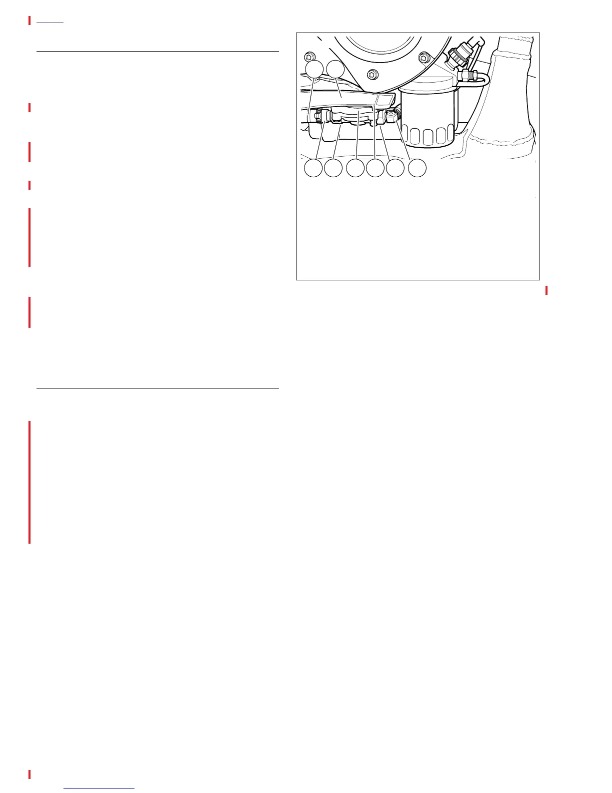
Figure 3-91. Oil Pump Hardware
a0024x3x
1
1. Feed Hose Connection
2. Return Hose
3. Feed Hose Clamp
4. Cover TORX Screw (2)
5. Oil Pump
6. Return Hose Clamp
7. Mounting Screw and Washer (2)
8. Steel Line Connection
2
3 6 7 84 5