2002 Buell P3: Engine 3-51
HOME
ASSEMBLY/INSTALLATION
NOTE
Liberally coat all moving parts with clean engine oil to ensure
easy assembly and smooth operation at start-up.
1. See Figure 3-90. Install gear shaft through body. Position
thrust washer over end of shaft. Install
new
retaining ring
into groove in shaft.
2. Insert inner gerotor of the gerotor scavenge set over
gear shaft.
3. Place outer gerotor over inner gerotor to complete scav-
enge set.
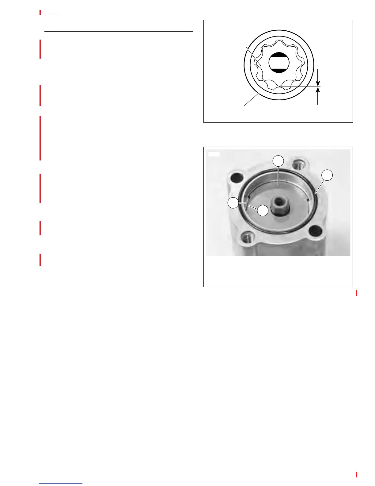
4. See Figure 3-93. Install gerotor separator plate by lining
up slots on perimeter with tabs inside oil pump body.
5. Install a
new
O-ring into groove in pump body.
6. See Figure 3-90. Place gerotor feed set over gear shaft.
7. Place cover onto pump body. Install cover TORX screws.
Tighten to 70-80
in-lbs
(8-9 Nm).
8. Place
new
mounting gasket in position.
NOTE
Use
new
hose clamps. If fittings were removed, use
TEFLON® PIPE SEALANT or HYLOMAR® on fitting threads.
9. See Figure 3-91. Attach return hose connection.
10. Secure pump to crankcase with mounting screws.
Tighten to 125-150
in-lbs
(14-17 Nm).
11. Attach feed hose and oil filter hose connection.
12. Attach clamp to hose.
13. Install
new
oil filter. See 1.5 ENGINE LUBRICATION
SYSTEM.
14. See 1.5 ENGINE LUBRICATION SYSTEM. Check
engine oil level. Add oil to correct level if needed.
Figure 3-92. Gerotor Wear Limits
Figure 3-93. Separator Plate Slots
Inner Gerotor
a0090x3x
Outer Gerotor
Wear
Limit
1
6620
2
3
1. Gerotor Separator Plate
2. Slot on Separator Plate
3. Tab on Oil Pump Body
4. O-ring
4