B-6 Appendix B: Wiring
HOME
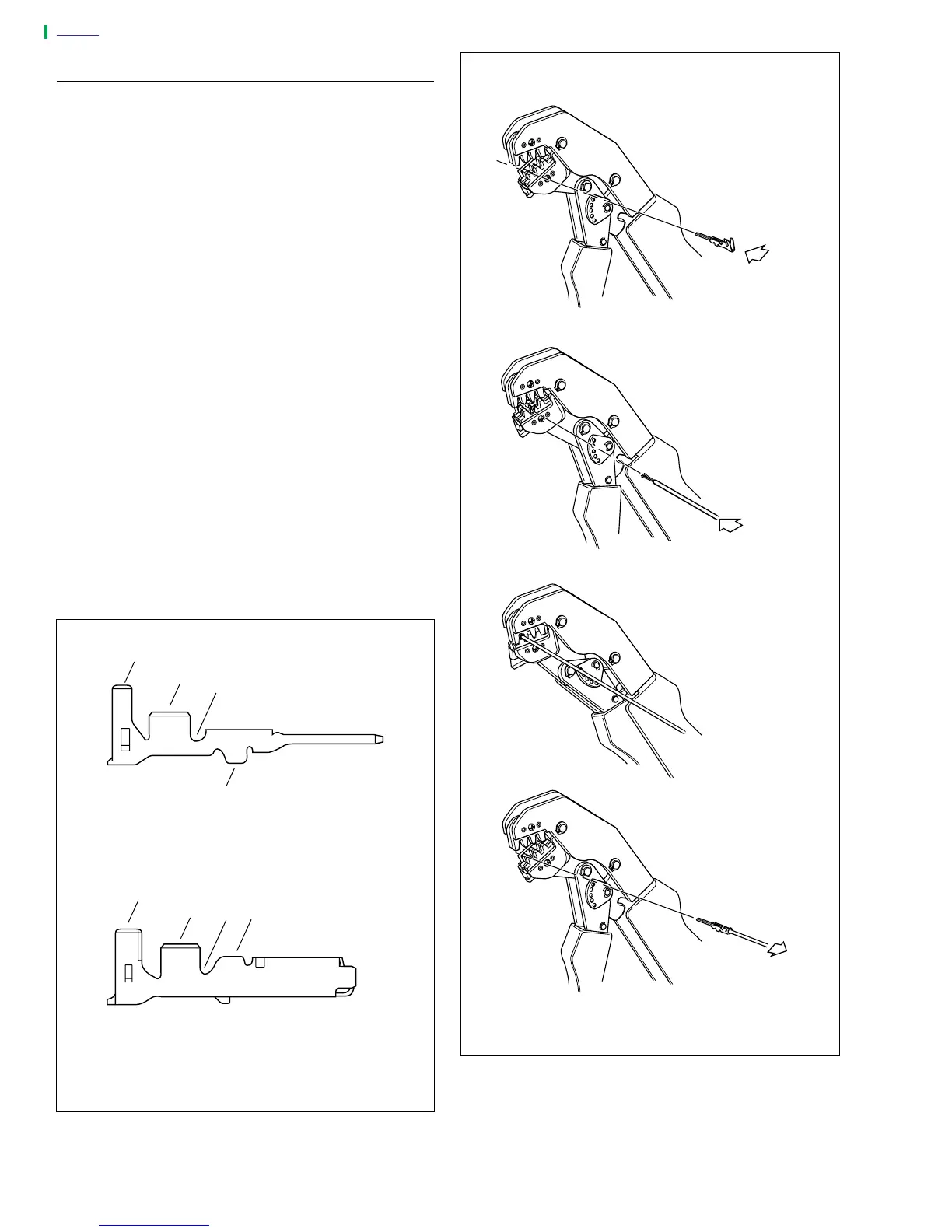
CRIMPING INSTRUCTIONS
1. See Figure B-9. Squeeze the handles to cycle the AMP
TERMINAL CRIMP TOOL (Part No. HD-41609) to the
fully open position.
2. Raise locking bar by pushing up on bottom flange. With
the crimp tails facing upward, insert contact (socket/pin)
through locking bar, so that the closed side of the contact
rests on the nest (concave split level area) of the crimp
tool). Use the front nest for 20 gauge wire, the middle for
16 gauge and the rear for 18 gauge.
3. Release locking bar to lock position of contact. When
correctly positioned, the locking bar fits snugly in the
space at the front of the core crimp tails.
4. Strip lead removing 0.1562 in. (4.0 mm) of insulation.
Insert wires between crimp tails until ends make contact
with locking bar. Verify that wire is positioned so that
short pair of crimp tails squeeze bare wire strands, while
long pair folds over insulation material.
5. Squeeze handle of crimp tool until tightly closed. Tool
automatically opens when the crimping sequence is
complete. Raise up locking bar and remove contact.
6. See Figure B-8. Inspect the quality of the core and insu-
lation crimps. Distortion should be minimal.
Figure B-8. Crimps
a0274x7x
1
2
3
4
1
2
3 4
Pin Terminal
Socket Terminal
1. Insulation Crimp Tail
2. Core Crimp Tail
3. Locking Groove Bar
4. Tang Slot
Figure B-9. Amp Multilock Crimping Procedure
a0273x7x
1. Raise locking bar and
seat contact on nest of
crimp tool. Release
locking tool.
2. Insert stripped lead
until it contacts locking
bar.
3. Close and squeeze
crimp tool.
4. Raise locking bar and
remove contact