Appendix B: Wiring B-5
HOME
INSTALLING SOCKET/PIN
TERMINALS
NOTES
●
For wire location purposes, numbers are stamped into
the secondary locks of both the socket and pin housings.
●
The tang in the chamber engages the slot to lock the ter-
minal in position.
●
On the pin side of the connector, tangs are positioned at
the bottom of each chamber, so the slot in the pin termi-
nal (on the side opposite the crimp tails) must face down-
ward.
●
On the socket side, tangs are at the top of each cham-
ber, so the socket terminal slot (on the same side as the
crimp tails) must face upward.
●
Up and down can be determined by the position of the
release button (used to separate the pin and socket
halves), the button always being the top of the connector.
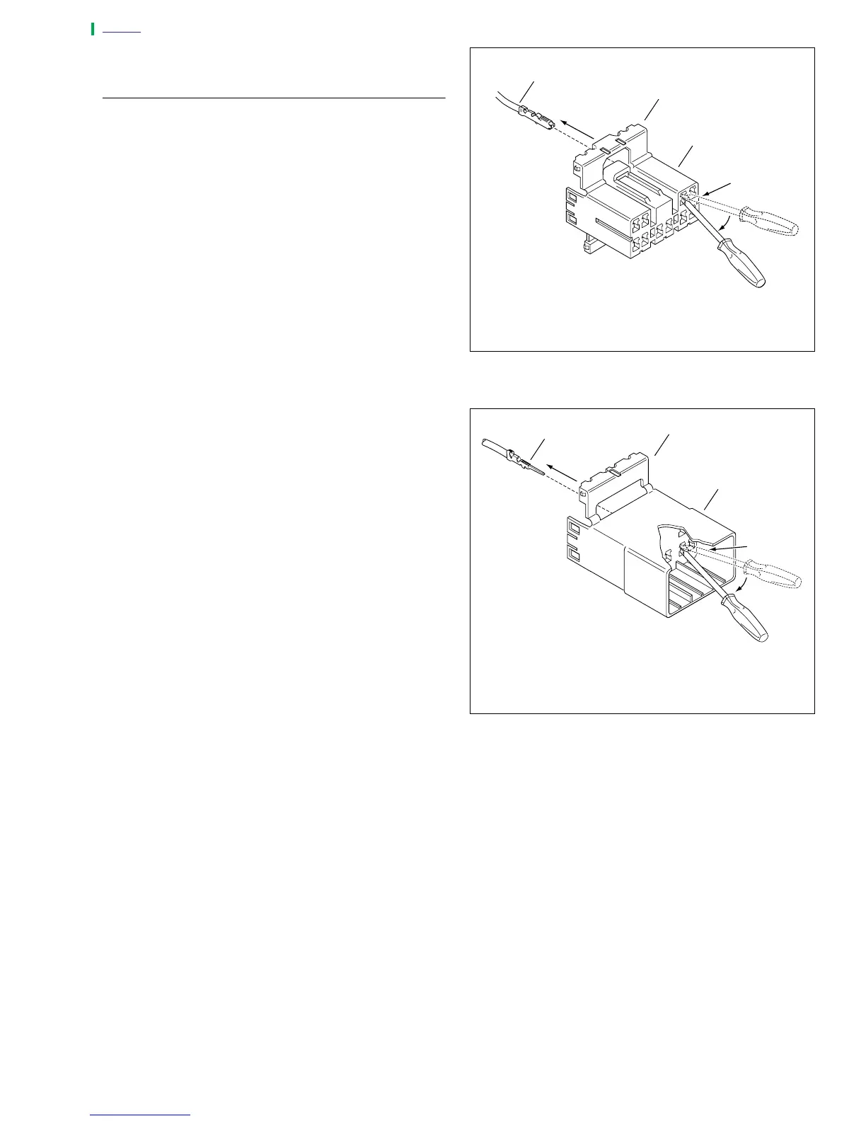
1. From the secondary lock side of the connector, insert the
terminal into its respective numbered chamber until it
snaps in place. For proper fit, the slot in the terminal
must face the tang in the chamber.
a. If installing socket terminals, see Figure B-6.
b. If installing pin terminals, see Figure B-7.
2. Gently tug on wire end to verify that the terminal is
locked in place and will not back out of chamber.
3. Rotate the hinged secondary lock inward until tabs fully
engage latches on both sides of connector.
4. Insert the socket housing (plug) into the pin housing
(receptacle) until it snaps in place.
5. Secure wiring harness with
new
cable straps.
Figure B-6. Socket Terminals
Figure B-7. Pin Terminals
1. Secondary Lock Open
2. Socket Housing
3. Socket Terminal
a0271x7x
1
3
2
A
B
C
1. Secondary Lock Open
2. Pin Housing
3. Pin Terminal
2
A
1
3
B
C
a0272x7x