2002 Buell P3: Drive/Transmission 6-17
HOME
Primary Chain/Drive
11WARNING1WARNING
To protect against shock and accidental start-up of vehi-
cle, disconnect the negative battery cable before pro-
ceeding. Inadequate safety precautions could result in
death or serious injury.
1. Remove negative battery cable from battery.
2. Remove primary cover. See 6.2 PRIMARY CHAIN.
3. Loosen engine sprocket.
a. Install SPROCKET LOCKING LINK (Part No. HD-
38362).
b. Remove the engine sprocket nut.
c. Loosen, but do not remove, engine sprocket. If nec-
essary, use the slotted portion of TWO CLAW
PULLER (Part No. HD-97292-61) and two bolts to
loosen the engine sprocket.
4. See Figure 6-23. Remove adjusting screw assembly.
a. Remove large retaining ring.
b. Remove adjusting screw assembly from pressure
plate.
CAUTION
See Figure 6-24. Mainshaft nut has left-hand threads. To
prevent damage, turn nut clockwise to loosen and
remove from mainshaft.
5. Remove mainshaft nut and washer.
6. Remove the clutch assembly, primary chain and engine
sprocket as a unit.
a. Inspect primary chain and sprockets for damage or
excessive wear.
b. Inspect stator and rotor. See 7.14 ALTERNATOR.
c. Replace damaged parts as necessary.
7. Install adjusting screw assembly into pressure plate.
a. See Figure 6-24. Align two tabs on perimeter of
release plate with corresponding recesses in pres-
sure plate.
b. See Figure 6-23. Secure the adjusting screw
assembly with large retaining ring.
8. Attach tools to compress clutch diaphragm spring. See
Step 2 of CLUTCH PACK under 6.6 PRIMARY DRIVE/
CLUTCH.
9. Remove clutch pack components. See Steps 3-4 of
CLUTCH PACK under 6.6 PRIMARY DRIVE/CLUTCH.
10. See Figure 6-21. Disassemble pressure plate.
a. Place a wrench on the clutch spring forcing screw
flats to prevent the forcing screw from turning.
b. Turn the compressing tool handle counterclockwise
until the handle spins off.
c. Remove washer, bearing and bridge.
d. Remove clutch spring forcing screw from clutch
adjusting screw.
e. Remove spring seat and diaphragm spring from
pressure plate.
11. See Figure 6-23. Remove and disassemble adjusting
screw assembly.
a. Remove large retaining ring.
b. Remove adjusting screw assembly from pressure
plate.
c. If necessary, disassemble adjusting screw assem-
bly. Remove and discard small retaining ring and
then separate the adjusting screw from the bearing
and release plate. Remove bearing from release
plate.
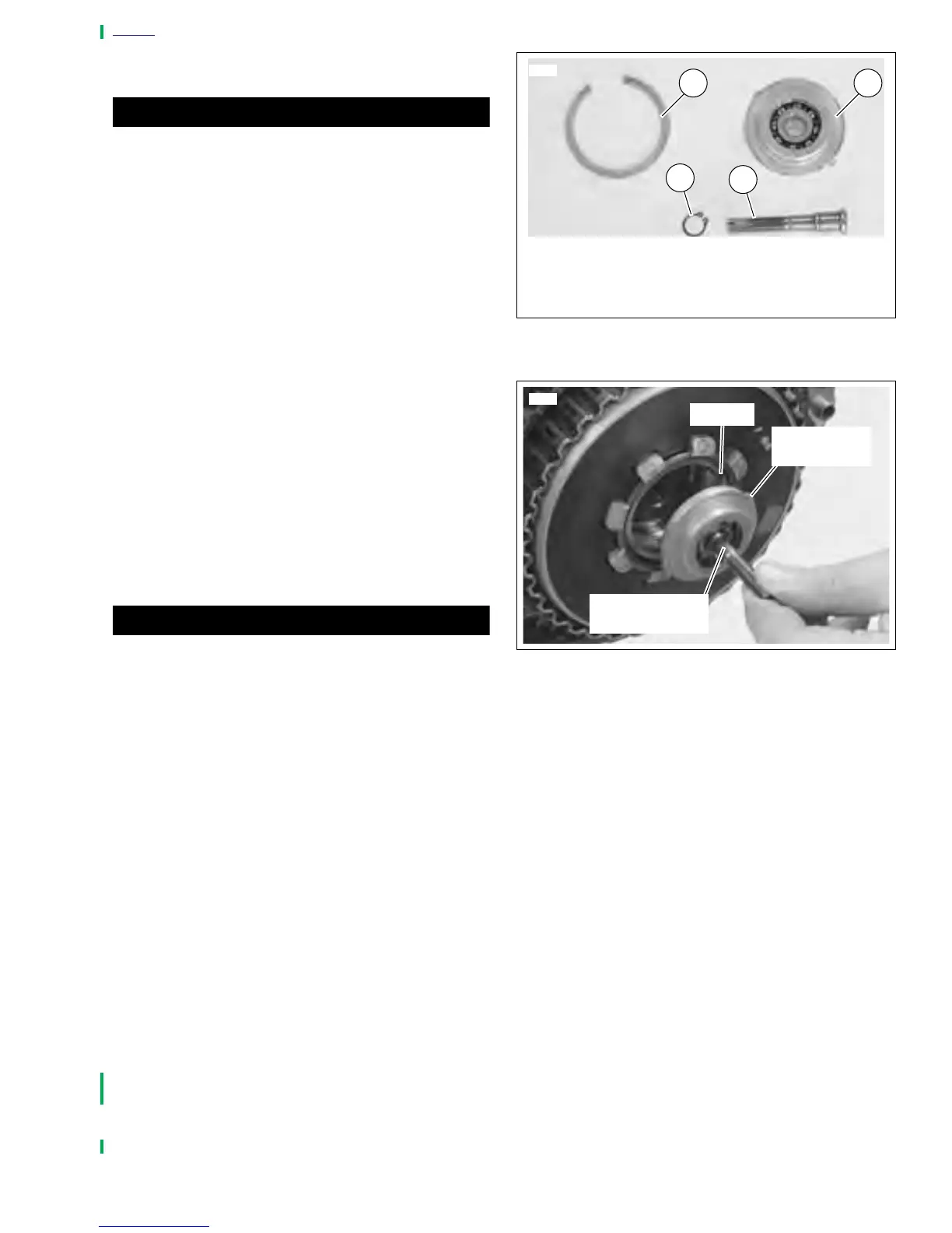
Figure 6-23. Adjusting Screw Assembly
Figure 6-24. Aligning Tabs
6251
1
1. Retaining Ring
2. Bearing and Release Plate
3. Retaining Ring
4. Adjusting Screw
2
3
4
6141
Tab on
release plate
Recess
Adjusting
screw assembly