6-20 2002 Buell P3: Drive/Transmission
HOME
INSTALLATION
NOTE
If clutch pack replacement was the only service work per-
formed, start with Step 5.
1. Install the engine sprocket, clutch assembly and primary
chain as a unit into primary chaincase.
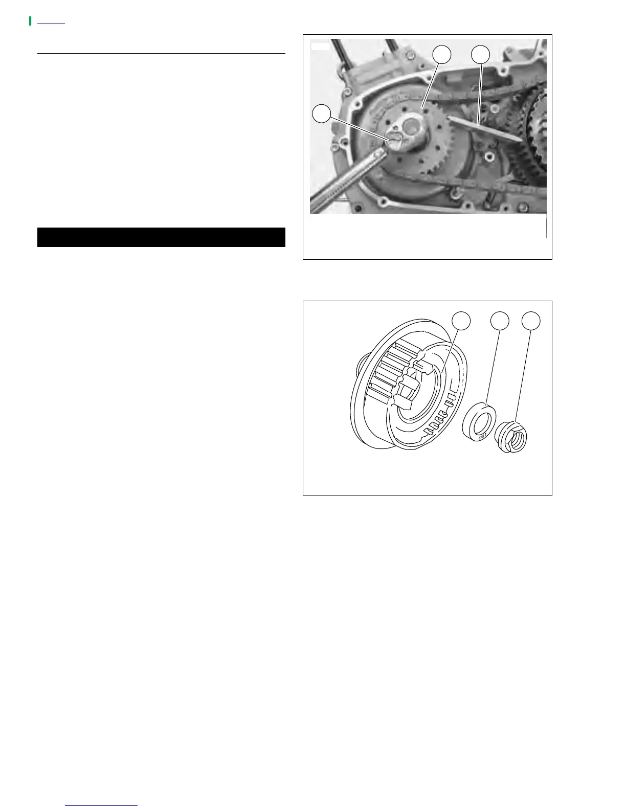
2. See Figure 6-29. Install the engine sprocket nut.
a. Place SPROCKET LOCKING LINK (Part No. HD-
38362) between primary chain and engine sprocket.
b. Apply two or three drops of LOCTITE
®
thread locker
262 (red) onto threads of sprocket shaft.
c. Install engine sprocket nut. Tighten to 190-210 ft-lbs
(258-285 Nm).
CAUTION
See Figure 6-30. Washer must be installed with the word
“out” facing the mainshaft nut or transmission may be
damaged.
3. Install mainshaft nut and washer.
a. Apply two or three drops of LOCTITE
®
thread locker
262 (red) onto threads on end of mainshaft.
b. Place washer on mainshaft with the word “out” fac-
ing away from clutch hub.
c. Install nut (left-hand threads). Tighten to 70-80 ft-
lbs (95-109 Nm).
4. Remove SPROCKET LOCKING LINK.
5. Install adjusting screw assembly into pressure plate.
a. See Figure 6-24. Align two tabs on perimeter of
release plate with corresponding recesses in pres-
sure plate.
b. See Figure 6-23. Secure the adjusting screw
assembly with retaining ring.
6. Install primary cover. See 6.2 PRIMARY CHAIN.
7. Install left footpeg support bracket. See 2.21 FOOT-
PEGS AND FOOTPEG SUPPORT BRACKETS.
8. Connect negative battery cable to battery terminal.
Tighten fastener to 60-96 in-lbs (7-11 Nm).
9. Install seat. See 2.28 SEAT.
Figure 6-29. Sprocket Locking Link
Figure 6-30. Mainshaft Nut and Washer
7692
1. Engine Sprocket
2. Torque Wrench
3. Sprocket Locking Link (Part No. HD-38362)
1 3
2
1. Mainshaft Nut
2. Washer
3. Clutch Hub
a0116x6x
1 2 3