2002 Buell P3: Electrical 7-11
HOME
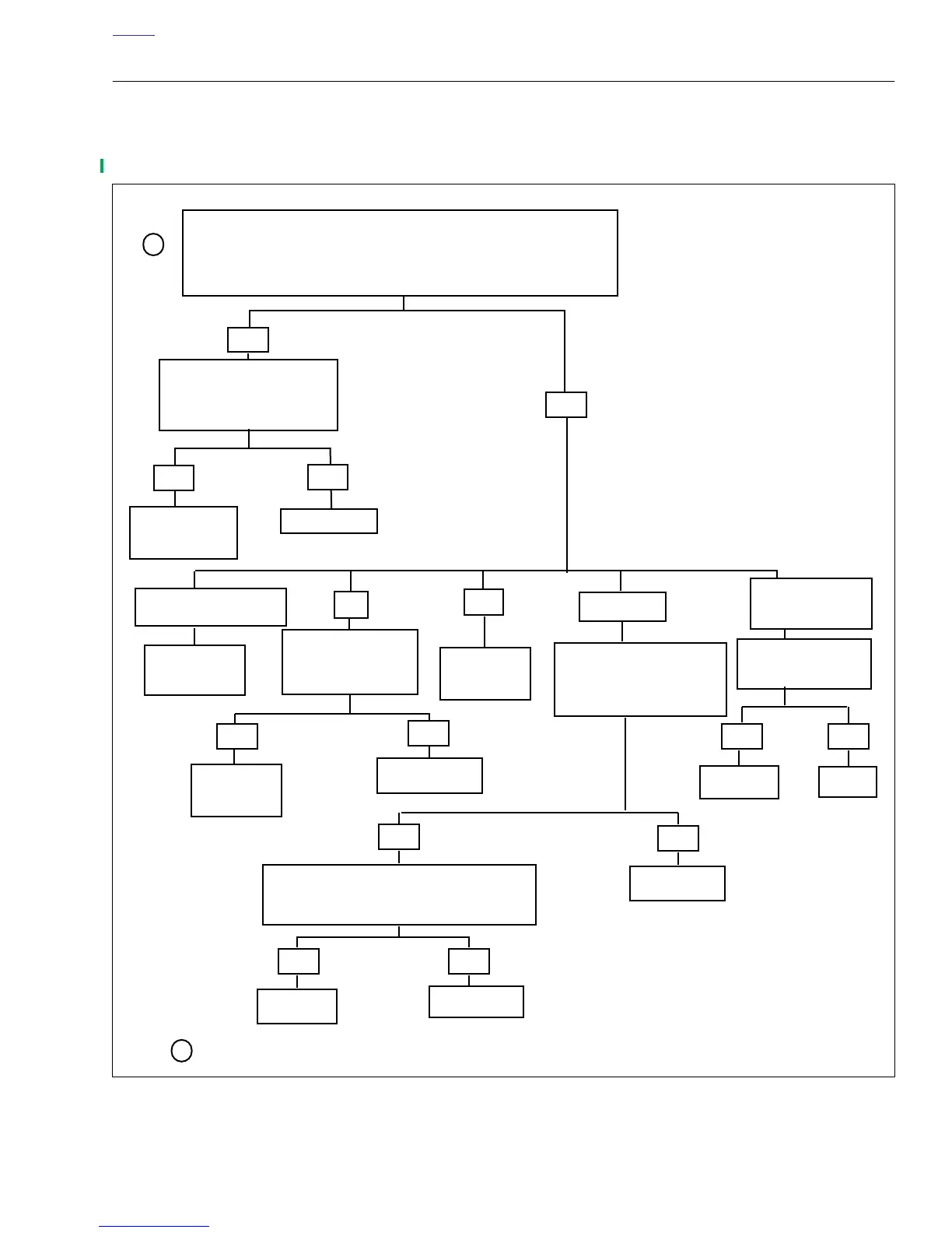
DRIVABILITY TROUBLESHOOTING
Poor Performance, Poor Fuel Economy,
Excessive Pinging
Figure 9. Drivability Troubleshooting
YES
NO
Check Timing. See Ignition
0V
12V
No Change
Erratic or
Locate and
Repair Short
Locate and
Repair Short
Check continuity between
breakout box pin 5 and
connector [88B] pin 5.
Continuity present?
Check connections.
Ter minals OK?
YES
NO
Check continuity between Breakout Box
Pin 3 and connector [88B] pins 3 and 4.
Continuity Present?
Repair Open
YES NO
Replace
TP Sensor
Repair Open
YES NO
Replace
TP Sensor
Repair
Module/Cam Position
Sensor for procedure.
NOTE
Male connectors are labeled “A”
Female connectors are labeled “B”
1
1
Remove seat and fuel tank cover. See 2.31 SEAT.
to ground.
to voltage.
7553
7605
7575
7595
7554
7610
7580
7590
Check resistance
Between Pin 3 and
ground. Is resistance
less than 1 ohm?
YES
Replace
Ignition Module
NO
7604
Is Timing Set Correctly?
YES
Check Auto-
Enrichener.
See Section 7.6
NO
Adjust Timing.
7553
Recalibrate TP
Sensor. See
Section 7.4.
>0.55V or <0.45V
Closed Throttle Voltage
Locate connector [88A] and [88B] on the carburetor. Remove Pin #3
on the harness side. Install Breakout Box Adaptor (HD-42962)
between [88A] and [88B]. Measure voltage between pin 3 and pin
5 on the Breakout Box. Voltage should change smoothly, slightly
above 0.5V (closed throttle) and below 3.7V (open throttle). Does it?
greater than 3.7V
and less than 12V