2002 Buell P3: Electrical 7-37
HOME
TESTING
Voltage Regulator Bleed Test
1. Be sure regulator is connected to battery. Check BK
charging wire on gold terminal of master circuit breaker.
2. Locate voltage regulator connector [46] behind left foot-
rest support. Disconnect from alternator stator wiring.
Cut cable tie and note its location.
3. Check regulator connector using a trouble light.
a. Touch one probe to a suitable ground.
b. Touch the other to the regulator pins, one at a time.
c. If light glows, replace regulator.
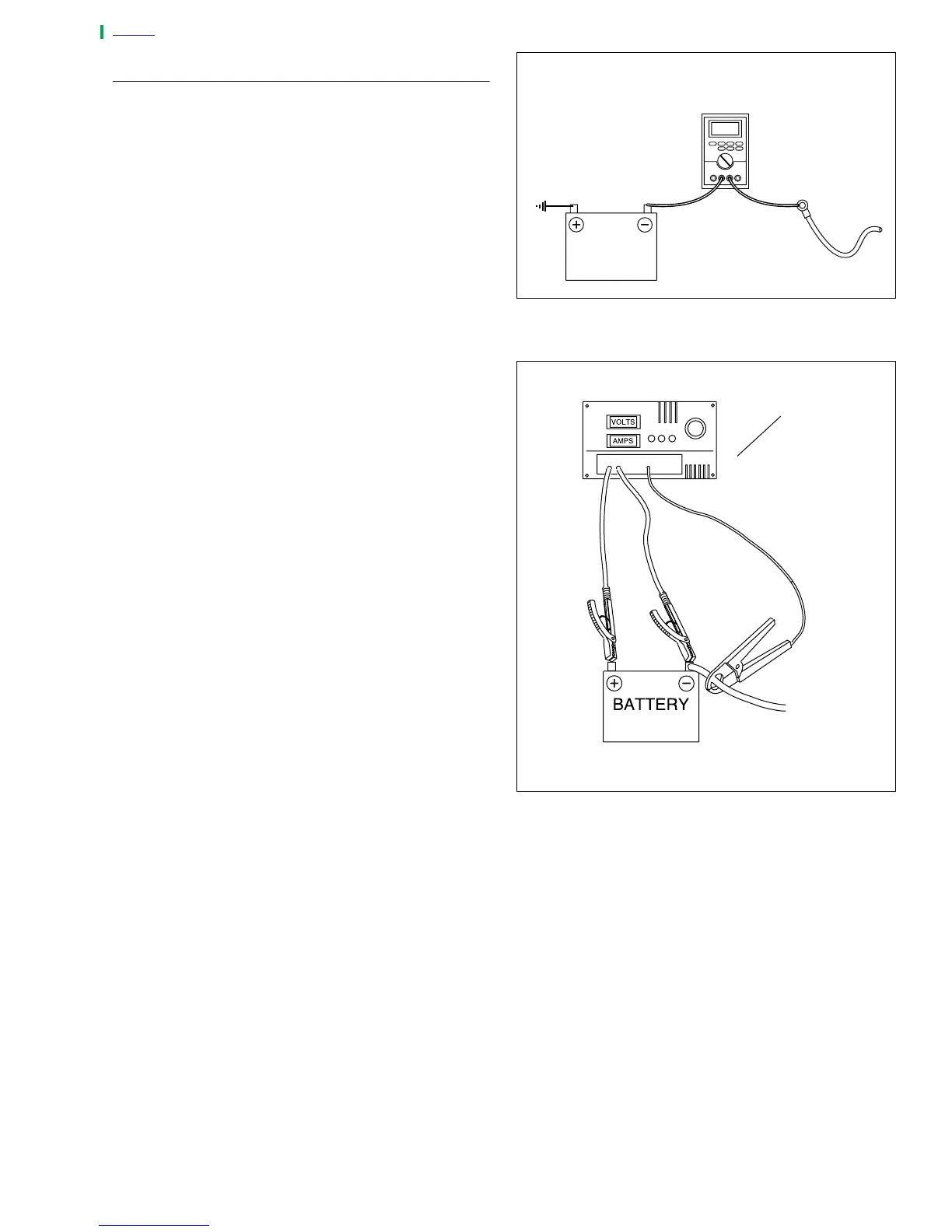
Milliampere Draw Test
NOTE
Be sure accessories are not wired so they stay on at all
times. This condition could drain battery completely if vehicle
is parked for a long time. Check for this by connecting amme-
ter between negative battery terminal and battery.
1. See Figure 7-42. Connect ammeter between negative
battery terminal and battery. With this arrangement, you
will also pick up any regulator drain.
2. With ignition key switch turned to OFF and all lights and
accessories off, observe amperage reading.
a. Maximum reading should be 1 milliampere.
b. A higher reading indicates excessive current draw.
Any accessories must be considered and checked
for excessive drain.
NOTE
A battery with a surface discharge condition could suffer a
static drain. Correct by cleaning battery case.
Total Current Draw Test
If battery runs down during use, the current draw of the
motorcycle components and accessories may exceed output
of the charging system.
1. See Figure 7-43. To check for this condition, place load
tester induction pickup or current probe pickup over bat-
tery negative cable.
2. Disconnect stator wiring from voltage regulator wiring at
the connector [46]. Start the motorcycle and run the
engine at 2000 RPM.
3. With ignition and all continuously running lights and
accessories turned on (headlamp on high beam), read
the total current draw.
4. Compare this reading to the reading obtained after per-
forming the
CURRENT AND VOLTAGE OUTPUT TEST
.
a. The current output should exceed current draw by
3.5 amps minimum.
b. If output does not meet specifications, there may be
too many accessories for the charging system to
handle.
5. Reconnect regulator after testing. Replace cut cable tie.
Figure 7-46. Milliampere Draw Test
Figure 7-47. Check Current Draw (Ignition Switch ON)
a0240x7x
12 VDC
battery
Ignition turned
to OFF
Battery negative
cable
1 milliampere
maximum
a0241x7x
Load tester