7-52 2002 Buell P3: Electrical
HOME
Rear
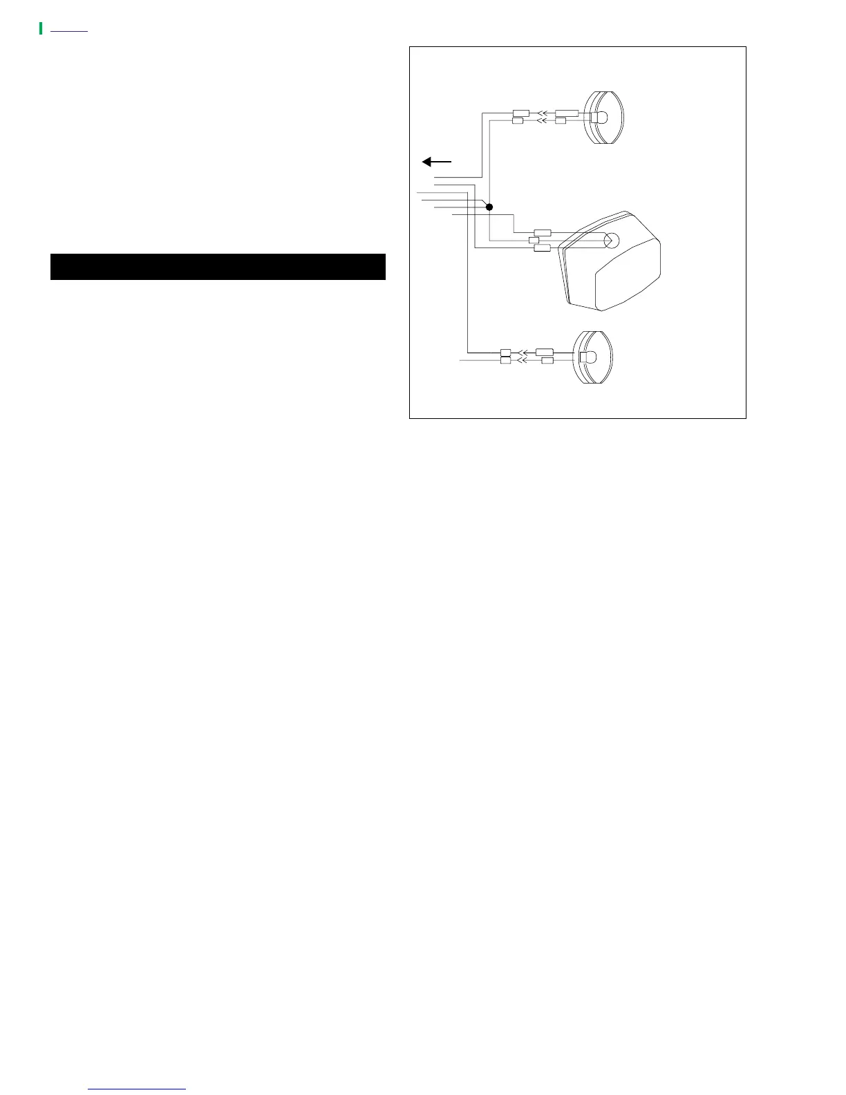
1. See Figure 7-71. Insert bullet connectors through rear
hole in tail lamp bracket. Attach turn signal using lock-
washer and nut. Tighten nut to 25-28 in-lbs (2.8-3.2
Nm).
NOTE
Install turn signal with lens drain hole facing downward.
2. Attach two bullet connectors on turn signal wires as
shown in Figure 7-72.
3. Use new cable strap to bundle turn signal wires beneath
tail section.
11WARNING1WARNING
Check for proper turn signal operation before riding
motorcycle. Visibility is a major concern for motorcy-
clists. Failure to have proper turn signal operation could
result in death or serious injury.
4. Check turn signals for proper operation. If operation fails,
reread procedure and verify that all steps were per-
formed.
a. Turn ignition key switch to IGN.
b. Activate left turn signals using switch on left handle-
bar. Front and rear left turn signals must flash.
c. Activate right turn signals using switch on left han-
dlebar. Front and rear right turn signals must flash.
d. Turn ignition key switch to OFF.
Figure 7-72. Rear Turn Signal Connections
R/Y
O/W
BK
BN
LT.BE
BK BE
BK
R/BK
BE
V
S18
a0258x7x
Right rear
directional lamp
Left rear
directional
lamp
Tail lamp
To [7]