2002 Buell P3: Electrical 7-55
HOME
11WARNING1WARNING
Check all handlebar switch operations before riding
motorcycle. Handlebar switches not operating properly
could result in death or serious injury.
5. Check handlebar switch for proper operation. If operation
fails, reread procedure and verify that all steps were per-
formed.
a. Turn ignition key switch to IGN.
b. Start motorcycle.
c. Turn ignition key switch to OFF.
Left Side
1. Attach switch housing to handlebar with three screws.
Tighten screws to 25-33 in-lbs (2.8-3.7 Nm).
2. See Figure 7-76. Route switch housing wiring harness
between front forks. Attach connector [24] and connector
[95] to wiring harness. Fasten wiring harness behind
dash with new cable straps.
11WARNING1WARNING
Check all handlebar switch operations before riding
motorcycle. Handlebar switches not operating properly
could result in death or serious injury.
3. Check handlebar switch for proper operation. If operation
fails, reread procedure and verify that all steps were per-
formed.
a. Turn ignition key switch to IGN.
b. Check headlamp LOW and HIGH beam settings.
c. Set headlamp to LOW beam. Press passing lamp
switch. Headlamp should flash HIGH beam for as
long as the switch is pressed.
d. Check left and right turn signals.
e. Activate horn by pressing horn switch.
f. Turn ignition key switch to OFF.
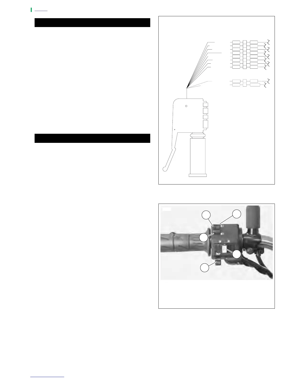
Figure 7-76. Left Handlebar Switch Connection
Figure 7-77. Left Handlebar Switches
V
GY
LBE
O
2
BE
GN
BK
BN
W
RIGHT TURN
9
8
7
6
5
3
1
W
Y/BK
V/BN
BN
O
Y
BE
HORN POWER
LEFT TURN
FROM FLASHER
HIGH BEAM
HORN
LIGHT POWER
LOW BEAM
R/BE
TN/GN
BK
2
1
BK
TO GROUND
TO STARTER RELAY
a0260x7x
Clutch Switch [95]
Left Handlebar Switch [24]
1. Passing Lamp
2. HIGH Beam
3. LOW Beam
4. Turn Signals
5. Horn
1
2
4
5
3
7079