7-60 2002 Buell P3: Electrical
HOME
REMOVAL
1. See Figure 7-83. Remove two fasteners holding dash
panel to upper triple clamp.
2. Unplug connector [20]. Cut and remove cable tie.
3. The rubber mount is a tight fit in the dash panel. To
remove the speedometer without damaging the dash
panel:
a. See Figure 7-84. Loosen screw until head is approx-
imately
1
/
8
inch above the back surface of the dash.
b. Liberally apply glass cleaner around circumference
of rubber mount.
c. See Figure 7-85. Position dash and speedometer on
edge of hard surfaced bench and apply even pres-
sure to dash to open a gap between the speedome-
ter and dash.
d. Remove two screws that secure speedometer to
rear of dash panel.
e. Apply more glass cleaner in gap and work speed-
ometer free from dash.
4. Depress tab and remove speedometer connector [39].
INSTALLATION
1. Install connector [39] on back of speedometer.
2. Lubricate rubber mount with glass cleaner and insert
speedometer into dash panel.
3. Install speedometer to dash panel with two screws in
back of dash panel.
4. Connect connector [20] and replace cable tie to adjacent
wire bundle.
5. Apply LOCTITE THREADLOCKER 243 (Blue) to first few
threads of dash panel mounting screws.
6. Position dash panel in mounting position on upper triple
clamp and install two screws. Tighten screws to 30-36
in-lbs (3-4 Nm).
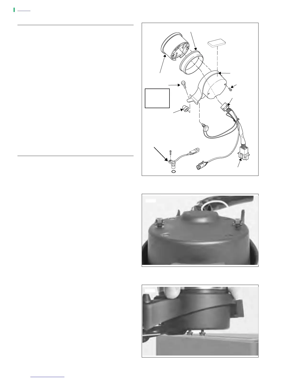
Figure 7-83. Speedometer
Figure 7-84. Speedometer Fasteners
Figure 7-85. Removing Speedometer
a0154x2x
Rubber Mount
Speedometer
Screws (2)
Dash Panel
Screws (2)
Connector [39]
Connector [20]
Speedometer
Speed Sensor
Reset Switch
Rubber Boot
30-36 in-lbs
(3-4 Nm)
Loctite 243
(Blue)
7748
7749